Supercharge Your Innovation With Domain-Expert AI Agents!

Image-effect method and image-effect apparatus

a technology of image-effect and apparatus, applied in the field of image-effect methods and apparatuses, can solve the problems requiring expensive equipment, and requiring only low-quality output, etc., and achieves the effect of reducing the amount of computation relative to s

Inactive Publication Date: 2003-01-23
MONOLITH
View PDF10 Cites 8 Cited by
  • Summary
  • Abstract
  • Description
  • Claims
  • Application Information

AI Technical Summary

Benefits of technology

[0069] Using a set of new multiresolutional filters called critical point filters, image matching is accurately computed. There is no need for any prior knowledge concerning the content of the images or objects in question. The matching of the images is computed at each resolution while proceeding through the resolution hierarchy. The resolution hierarchy proceeds from a coarse level to a fine level. Parameters necessary for the computation are set completely automatically by dynamical computation analogous to human visual systems. Thus, There is no need to manually specify the correspondence of points between the images.
[0234] (3) In the base technology, four types of submappings related to four types of critical points are generated at each level of resolution. However, one, two, or three types among the four types may be selectively used. For instance, if there exists only one bright point in an image, generation of hierarchical images based solely on f.sup.(m,3) related to a maxima point can be effective to a certain degree. In this case, no other submapping is necessary at the same level, thus the amount of computation relative on s is effectively reduced.

Problems solved by technology

Thus, a barrier that had previously existed between broadcasting and communications is quickly beginning to disappear.
However, many of these effects require expensive equipment that may be difficult to operate or require extensive human input or provide only low quality output.
In particular, if the detecting is based on whether the energy level of the two compared pixels is low or not, the penalty may be to add a high value to the energy level.

Method used


Image

  • Image-effect method and image-effect apparatus
  • Image-effect method and image-effect apparatus
  • Image-effect method and image-effect apparatus

Examples


Embodiment Construction

Concerning Image-effect

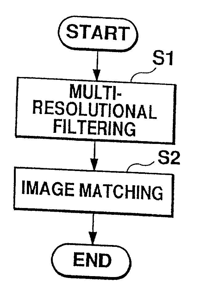
[0238] An image-effect technology utilizing the above base technology and according to an embodiment of the invention will now be described with reference to FIGS. 18-20. In this embodiment, generation of a morphing or motion pictures by image matching between two key frames is performed. In combination with the above-described base technology, very smooth motion pictures may be generated with relatively few key frames or with key frames that are very different from each other, such that, this technology also provides high data compression for motion pictures.

[0239] FIG. 18 shows a first image I1 and a second image I2, which represent key frames. A user of an image-effect apparatus 10 (as described below with reference to FIG. 20), sets a first region R1 in the first image I1 and a second region R2 in the second image I2 that are meant to correspond to each other. That is, the user instructs the image-effect apparatus 10 that the first region R1 should corresp...


PUM


Abstract

An image input unit acquires a first image and a second image. A region setting unit sets a first region within the first image and a second region within the second image. A matching processor performs a matching computation between the first image and the second image. More specifically, the matching processor performs the matching computation between the first image and the second image using an internal constraint process for constraining the first region to be more likely to correspond to the second region.

Description

[0001] 1. Field of the Invention[0002] The present invention relates to image-effect techniques and more particularly relates to a method and apparatus for digital image effects.[0003] 2. Description of the Related Art[0004] As a part of the digital revolution, many users have come to enjoy services on the Internet from personal computers and portable telephones. The digital revolution is now spreading to broadcast services and movies, including digital satellite broadcasts. Thus, a barrier that had previously existed between broadcasting and communications is quickly beginning to disappear. Moreover, as broadband communications grow, multimedia content and culture will experience significant development, and, as a part of this multimedia culture, the distribution of video or motion pictures will become a key technology.[0005] When humans acquire information from the outside world, images are capable of conveying much more information than audio. Besides being used for entertainment...

Claims


Application Information

Patent Timeline
IPC IPC(8): G06T7/00G06T5/50H04N19/00H04N19/20H04N19/30H04N19/51H04N19/59H04N19/597H04N19/80
CPCG06T7/0026G06T7/0028G06T2207/20016G06T2207/20021G06T7/32G06T7/33
Inventor SHINAGAWA, YOSHIHISANAGASHIMA, HIROKI
Owner MONOLITH
Features
  • R&D
  • Intellectual Property
  • Life Sciences
  • Materials
  • Tech Scout
  • Unparalleled Data Quality
  • Higher Quality Content
  • 60% Fewer Hallucinations
Learn More