Electric double layer capacitor

a double-layer capacitor and capacitor technology, applied in the direction of fixed capacitors, liquid electrolytic capacitors, electrochemical generators, etc., can solve problems such as an increase in internal resistan

Inactive Publication Date: 2010-05-18
SANYO ELECTRIC CO LTD
View PDF7 Cites 5 Cited by
  • Summary
  • Abstract
  • Description
  • Claims
  • Application Information

AI Technical Summary

Benefits of technology

[0012]In this electric double layer capacitor, the first conductive layer and the first electrode are electrically connected in a plurality of paths through the second conductive layer within the first opening portion and the second opening portion formed on the insulating layer. This maintains the electric connection when, for example, connection at one opening portion is maintained even if disconnection or connection failure occurred at another opening portion due to a separation of the first conducive layer and the second conductive layer, thus failures in electric connecting paths between the first conductive layer and the first electrode can be inhibited. As a result, an electric double layer capacitor which can inhibit an increase of internal resistance can be obtained.
[0014]In addition, the minimum value of opening widths for the first opening portion and the second opening portion described above may be formed larger than 50 μm. By configuring this way, a sufficient contact area for a first metal layer and a second metal layer can be taken. Also, less contact failures occur in production, thus, the decrease of yield in production can be inhibited.
[0015]Further, (Δβ×L2), the product of differences of each linear coefficient of expansion for the first conducive layer and second conductive layer, Δβ, and the maximum value of opening widths for the first opening portion and the second opening portion, L2, may be 0.0039 μm / ° C. or below. In addition, in the first invention, an average between approximately 0° C. and approximately 100° C. is used as a liner coefficient of expansion. By configuring this way, distortion in each opening portion due to thermal expansion of the first conductive layer and the second conductive layer from heating, such as solder reflow processes, can be reduced. This inhibits the separation of the first conductive layer and the second conductive layer within each opening portion. In addition, when the second conductive layer has a laminated structure comprising a plurality of metal materials, it is preferable to satisfy the above-mentioned relationship between the first conductive layer within each opening portion and its adjacent layers, and it is further preferable to satisfy the above-mentioned relationship between each adjacent layer.

Problems solved by technology

However, in the conventional electric double layer capacitor described above, there are problems of a separation between the first conductive layer 103 and the second conductive layer 105 when heated by processes, such as reflow soldering.
In this case, there is an issue of an increase in internal resistance for the conventional electric double layer capacitor described above.

Method used


Image

  • Electric double layer capacitor
  • Electric double layer capacitor
  • Electric double layer capacitor

Examples


embodiment 1

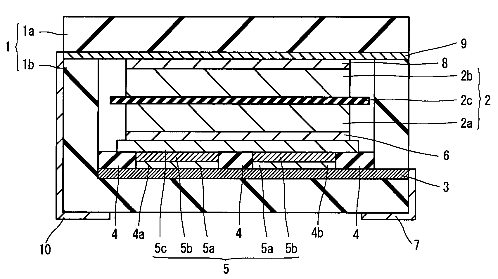
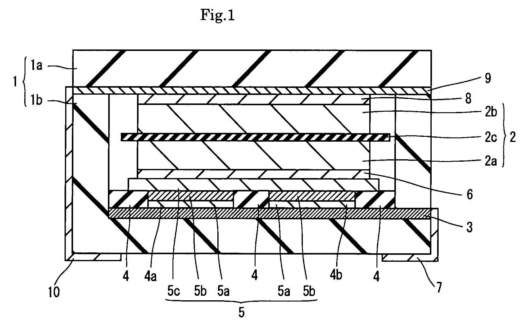
[0024]FIG. 1 is a cross-sectional diagram to explain the configuration of an electric double layer capacitor according to embodiment 1 of the present invention. FIG. 2 is an upper view of a container portion in concaved form for an electric double layer capacitor according to embodiment 1 of the present invention. The configuration of the electric double layer capacitor according to embodiment 1 of the present invention is hereinafter explained in reference to FIGS. 1 and 2.

[0025]In the electric double layer capacitor of the embodiment 1 of the present invention, as shown in FIG. 1, an electric double layer capacitor element 2 sandwiches a separator 2c comprised of glass fiber between a cathode 2a and an anode 2b, and is arranged inside a container 1 having a lid 1a comprised of kovar (which is comprised of cobalt: approximately 17 wt %, nickel: approximately 29 wt %, the rest: iron) and a containing portion 1b in a concaved form comprised of alumina. In addition, the cathode 2a and...

embodiment 2

[0047]As an embodiment 2, 20 cells of electric double layer capacitor which have similar constructions to that of embodiment 1 were fabricated, except that both of opening portions 4a and 4b were formed in square shapes of approximately 150 μm as described above, in comparative example 1. At this time, the minimum opening width of the opening portion, L1, is approximately 150 μm and the maximum opening width, L2, is approximately 212 μm. Also, (Δβ×L2) is approximately 0.0020 μm / ° C.

[0048]Next, a storage test for approximately 10 minutes at approximately 260° C. was conducted on 20 cells of each of the electric double layer capacitors fabricated for the comparative example 2-6 and embodiment 2. Thereafter, for each cell, internal resistances were measured at a frequency of approximately 1 kHz with an ohm tester to determine the ratio of degraded cells showing a value of 1000 Ohm or above. The results are shown in table 2.

[0049]

TABLE 2Number ofL1Δβ× L2Ratio ofopening portionsμmμm / ° C....


PUM


Abstract

The present invention provides an electric double layer capacitor. An electric double layer capacitor element sandwiches a separator between a cathode and an anode, arranged inside a container comprising a concave shaped containing portion and lid. A first conductive layer on the inner bottom face of a containing portion is covered by an insulating layer, and opening portions formed on the insulating layer penetrate to the first conductive layer. A second conductive layer is formed on the insulating layer and inside the opening portions, and is connected to a cathode through a conductive adhesive. The first conductive layer penetrates through the side wall of the containing portion, and is connected to a connecting terminal. An anode is connected to a third conductive layer through a conductive adhesive, and a collector is connected to a connecting terminal by extending between the containing portion and the lid.

Description

TECHNICAL FIELD[0001]The present invention relates to an electric double layer capacitor.BACKGROUND OF INVENTION[0002]Conventionally, an electric double layer capacitor has been proposed, the electric double layer capacitor is mountable on the surface of a printed wiring board of a mobile phone and so on. An example of such technology is described in the Japanese published unexamined patent application no. 2005-210064.[0003]FIG. 3 is a cross-section diagram to explain the configuration of a conventional electric double layer capacitor. The conventional electric double layer capacitor is hereafter explained in reference to FIG. 3.[0004]In the conventional electric double layer capacitor, as shown in FIG. 3, an electric double layer capacitor element 102, which sandwiches a separator 102c between a cathode 102a and an anode 102b, is arranged inside a sealed container 101 comprising a lid 101a and a concaved containing portion 101b comprised of ceramics, such as alumina.[0005]On the in...

Claims


Application Information

Patent Timeline
Patent Type & Authority Patents(United States)
IPC IPC(8): H01G9/00H01G11/00H01G11/22H01G11/24H01G11/28H01G11/38H01G11/42H01G11/66H01G11/70H01G11/74H01G11/86
CPCH01G9/016H01G9/06H01G9/155H01G11/74H01G11/80H01G11/82H01G11/70Y02E60/13
Inventor KATO, KIKUKONIKI, SACHINONOUE, HIROSHI
Owner SANYO ELECTRIC CO LTD
Why Eureka
Try Eureka