
Vehicle and control device for vehicle

a technology for controlling devices and vehicles, applied in electric devices, battery/fuel cell control arrangements, battery/cell propulsion, etc., can solve problems such as the inability of vehicles to obtain acceleration and the inability to meet driver requests, and achieve the effect of overcoming insufficient motor output torqu

Active Publication Date: 2014-06-26
TOYOTA JIDOSHA KK +1
View PDF5 Cites 6 Cited by
  • Summary
  • Abstract
  • Description
  • Claims
  • Application Information

AI Technical Summary

Benefits of technology

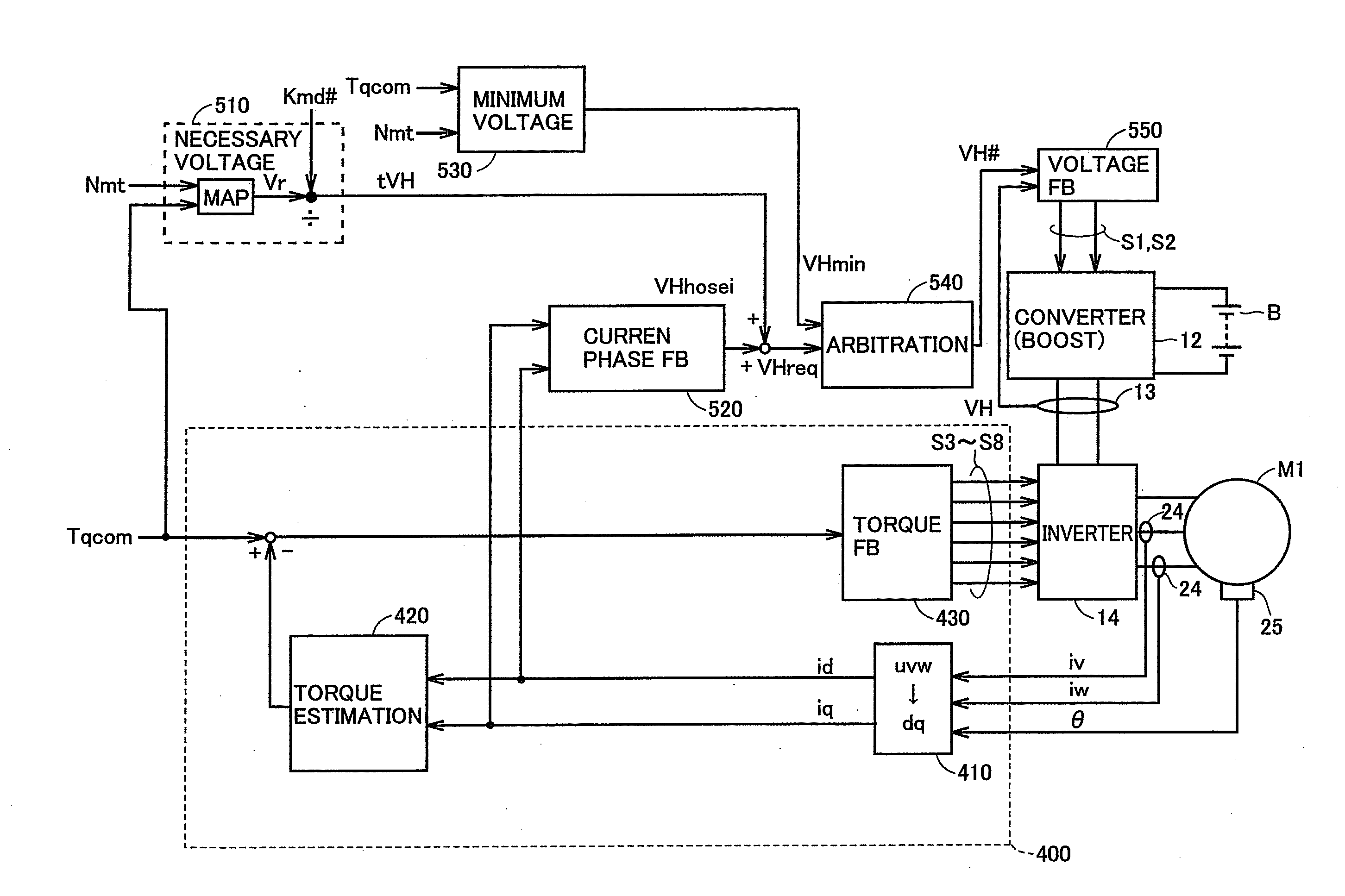
The patented invention prevents the motor from getting insufficient torque by controlling the output voltage from the converter. Rather than trying to achieve the target torque, the invention makes the output voltage close to the minimum voltage needed for achieving the target torque. This prevents the output voltage from the converter from dropping below the minimum level required for the motor. Overall, this invention ensures better performance of the motor and prevents it from getting insufficient torque.

Problems solved by technology

Accordingly, there may be a case that a vehicle cannot obtain acceleration and a request from a driver cannot be met.

Method used


Image

  • Vehicle and control device for vehicle
  • Vehicle and control device for vehicle
  • Vehicle and control device for vehicle

Examples


Embodiment Construction

[0027]An embodiment of the present invention will be described hereinafter in detail with reference to the drawings. It is noted that the same or corresponding elements in the drawings below have the same reference characters allotted and description thereof will not be repeated in principle.

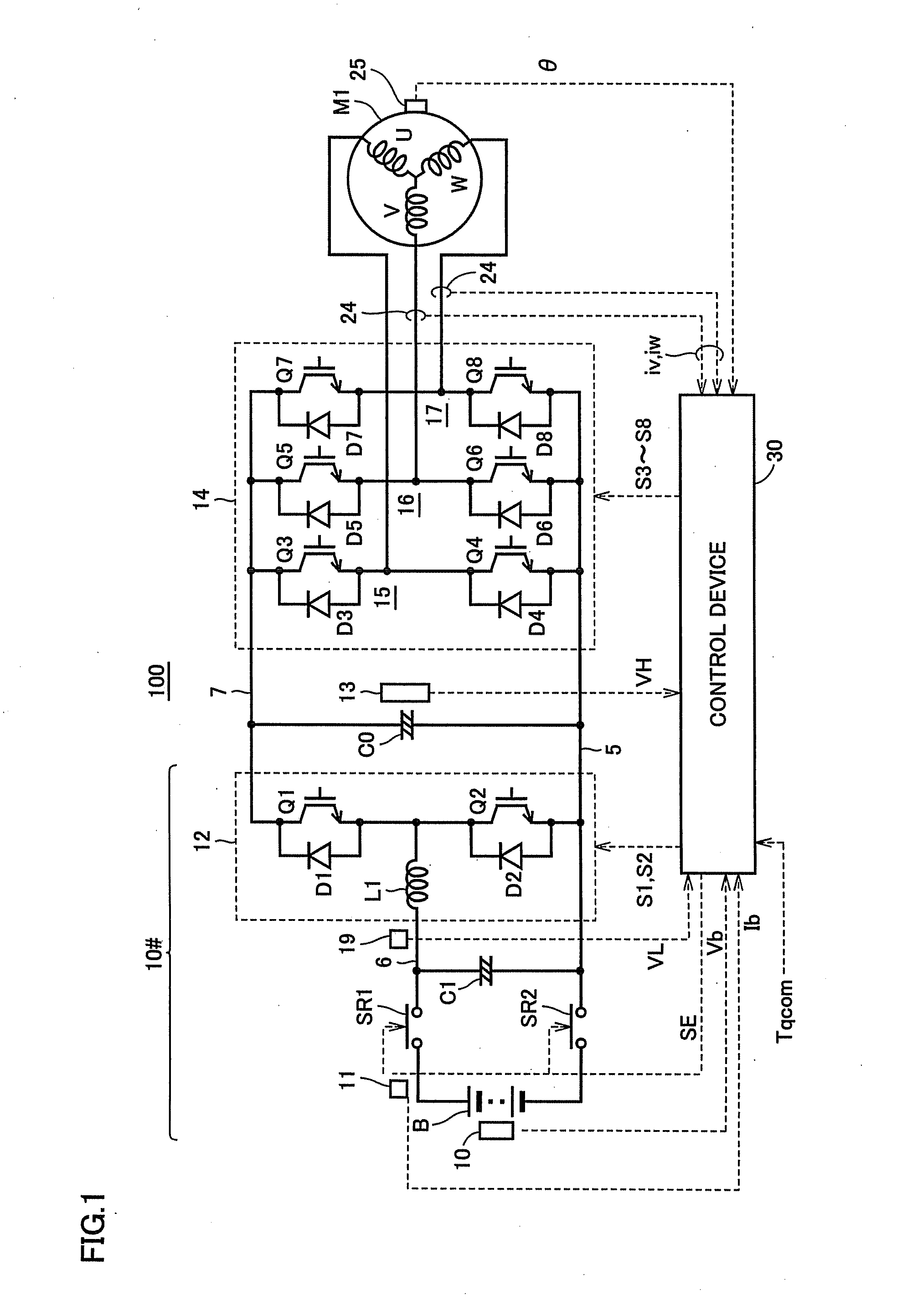
[0028]FIG. 1 is a diagram of an overall configuration of a control system 100 for an AC electric motor mounted as a drive source on a vehicle. Control system 100 includes a DC voltage generation portion 10#, a smoothing capacitor C0, an inverter 14, an AC electric motor M1, and a control device 30.

[0029]AC electric motor M1 is, for example, a traction motor for running configured to generate torque in a drive wheel of an electrically-powered vehicle (comprehensively expressing a car capable of generating vehicle driving force with electric energy, such as a hybrid car, an electric car, and a fuel cell car). Alternatively, this AC electric motor M1 may be configured to have a function as a genera...


PUM


Abstract

On a vehicle, a converter converting and outputting a voltage, an inverter converting DC power output from the converter to AC power, and a motor driven by AC power supplied from the inverter are mounted. A control device calculates a requested voltage VHreq as an output voltage from a converter for bringing a degree of modulation Kmd of the inverter closer to a prescribed target degree of modulation Kmd#, calculates from target torque of the motor, a minimum voltage VHmin as a minimum value for an output voltage from the converter which can realize target torque of the motor, and controls the converter such that the output voltage VH from the converter is closer to a value which is greater one of the requested voltage VHreq and the minimum voltage VHmin.

Description

[0001]This nonprovisional application is based on Japanese Patent Application No. 2012-280918 filed on Dec. 25, 2012 with the Japan Patent Office, the entire contents of which are hereby incorporated by reference.BACKGROUND OF THE INVENTION[0002]1. Field of the Invention[0003]The present invention relates to a control device for a vehicle, and particularly to a technique for controlling an output voltage from a converter in a vehicle incorporating a motor driven by electric power supplied through a converter and an inverter.[0004]2. Description of the Background Art[0005]A hybrid car, a fuel cell car, and an electric car which incorporate an electric motor as a drive source have been known. For example, a three-phase AC motor is employed as the electric motor. Such an electric motor is supplied with AC power from an inverter.[0006]Various techniques can be used for controlling an inverter. By way of example of a technique used for controlling an inverter, Japanese Patent Laying-Open...

Claims


Application Information

Patent Timeline
Patent Type & Authority Applications(United States)
IPC IPC(8): B60L11/00B60L50/16
CPCB60L11/00B60L7/14B60L15/007B60L15/025B60L15/2009B60L50/16B60L50/51B60L58/21B60L2210/14B60L2210/40B60L2240/421B60L2240/423B60L2240/547B60L2240/549B60L2250/26Y02T10/64Y02T10/70Y02T10/7072Y02T10/72
Inventor MORII, AKIYOSHINOMURA, TETSUYANAKAMURA, MAKOTOYAMAZAKI, MIKIO
Owner TOYOTA JIDOSHA KK
Learn More