
Method for automatic weapon allocation and scheduling against attacking threats

a technology of automatic weapon allocation and scheduling, applied in the field of systems and methods for allocating and scheduling resources, can solve the problems of not addressing the issue of when to deploy the weapon system against the threat, rendering some threats unengageable, and the weapon system can only guide a limited number of interceptors

Inactive Publication Date: 2003-01-30
RAYTHEON CO
View PDF0 Cites 52 Cited by
  • Summary
  • Abstract
  • Description
  • Claims
  • Application Information

AI Technical Summary

Benefits of technology

This approach ensures that all threats can be effectively engaged by optimizing the deployment times, preventing resource overload and achieving optimal engagement objectives even under heavy attack conditions, while reducing computational complexity through heuristic methods.

Problems solved by technology

While some of these approaches have used trial-intercept calculations to determine the window of engagement to determine a weapon system's effectiveness against a threat, they do not address the issue of when to deploy the weapon system against the threat in this window.
Since the first step did not model the engagement-time resource requirements and temporal constraints of the weapon systems, there is a possibility that this step may have assigned enough threats to a weapon system to overwhelm its time-dependent resources, possibly rendering some of the threats unengageable.
Since the number of such ground-based sensors is limited, a weapon system can only guide a limited number of interceptors at any time.
If the number of threats requiring simultaneous guidance exceeds this number, then the weapon system will not be able to engage all its threats.
The weapon system may then inform the operator about the situation and the operator may then pass it to another weapon system, possibly resulting in delay and even leaked threats.
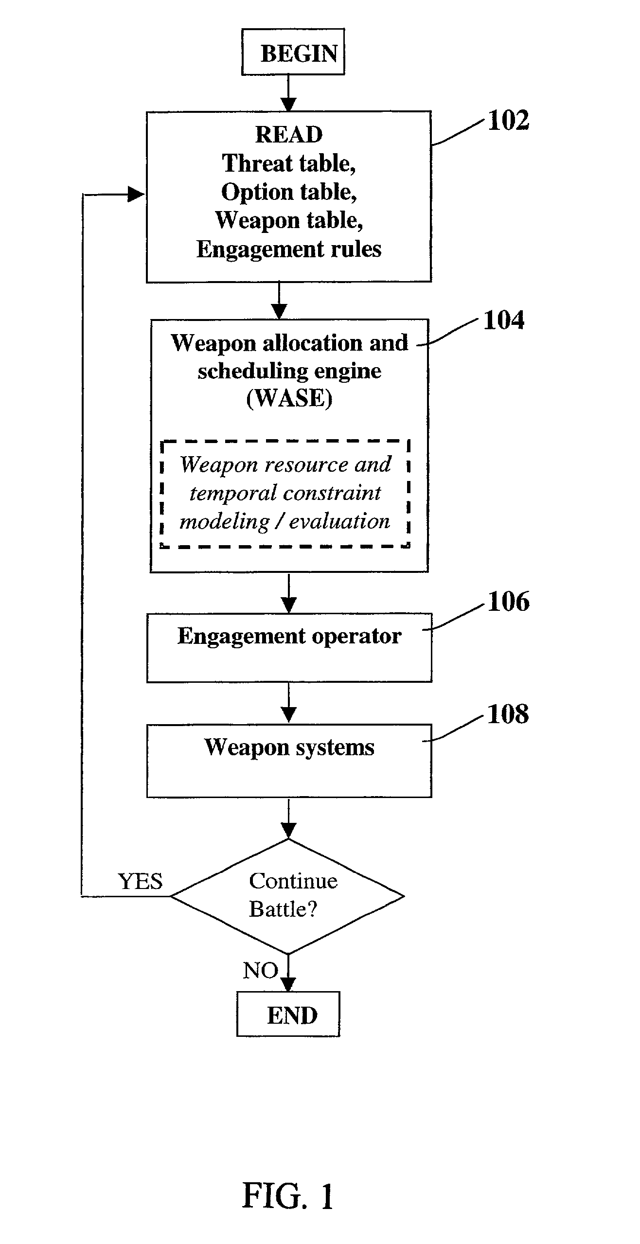
This sequential disconnected decision making process has two disadvantages: (1) since actual weapon resource requirements have not been modeled in the first step, weapon systems may end up being assigned more threats than they can engage, and, (2) consequently, there may be engagement delays and / or leaked threats (sub-optimal engagement).
As discussed before, none of these inventions optimize the deployment or launch time of the weapon system.
In short, none of these patents address and solve the problem of optimizing "when" to deploy the resources (weapon systems).
However, weapon system resource limitations during actual engagement of the threat when multiple threats are assigned to it are not considered.
These approaches do not determine whether the weapon system can actually engage the threats if several threats are assigned to this weapon system with each threat individually engagable by the weapon system based on battle-space calculations.
For example, if several threats have overlapping intercept time windows and each interceptor needs to be guided during some part of its flight from launch to intercept, then there may not be enough guidance sensors at this weapon system to guide interceptors to engage all threats assigned to it.
Thus, every threat may end up being assigned a weapon system in these methods, but every threat may actually not be engaged as its assigned weapon system may not have enough resources at engagement time.
Even if engagement time resources are considered in the allocation and scheduling, as in U.S. Pat. No. 5,404,516, optimal engagement objectives cannot be achieved without optimizing the time of allocation (scheduling) of these resources.
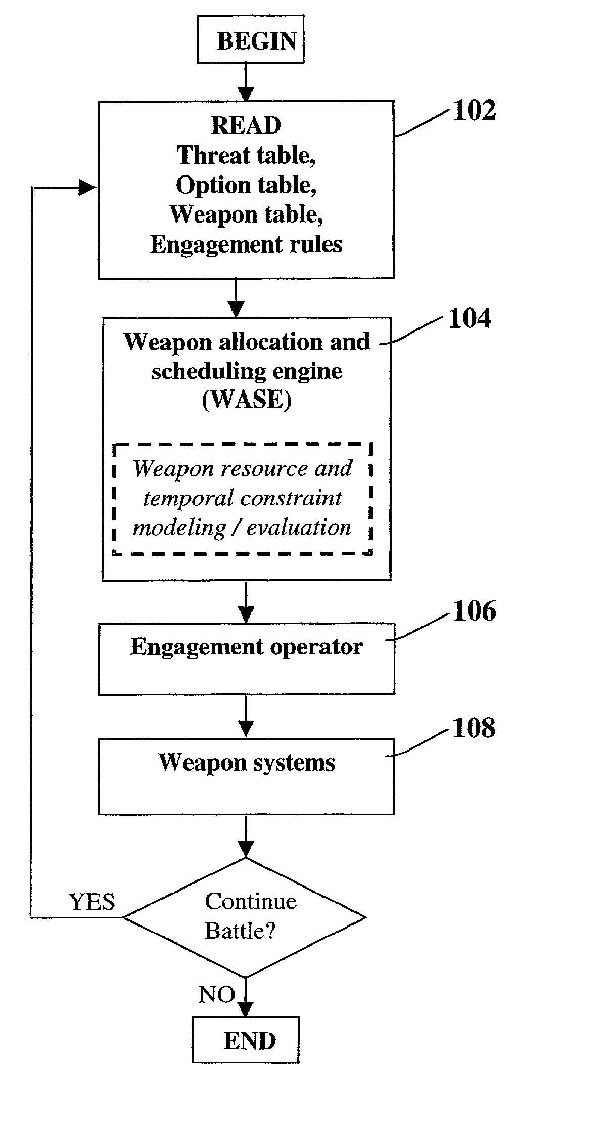
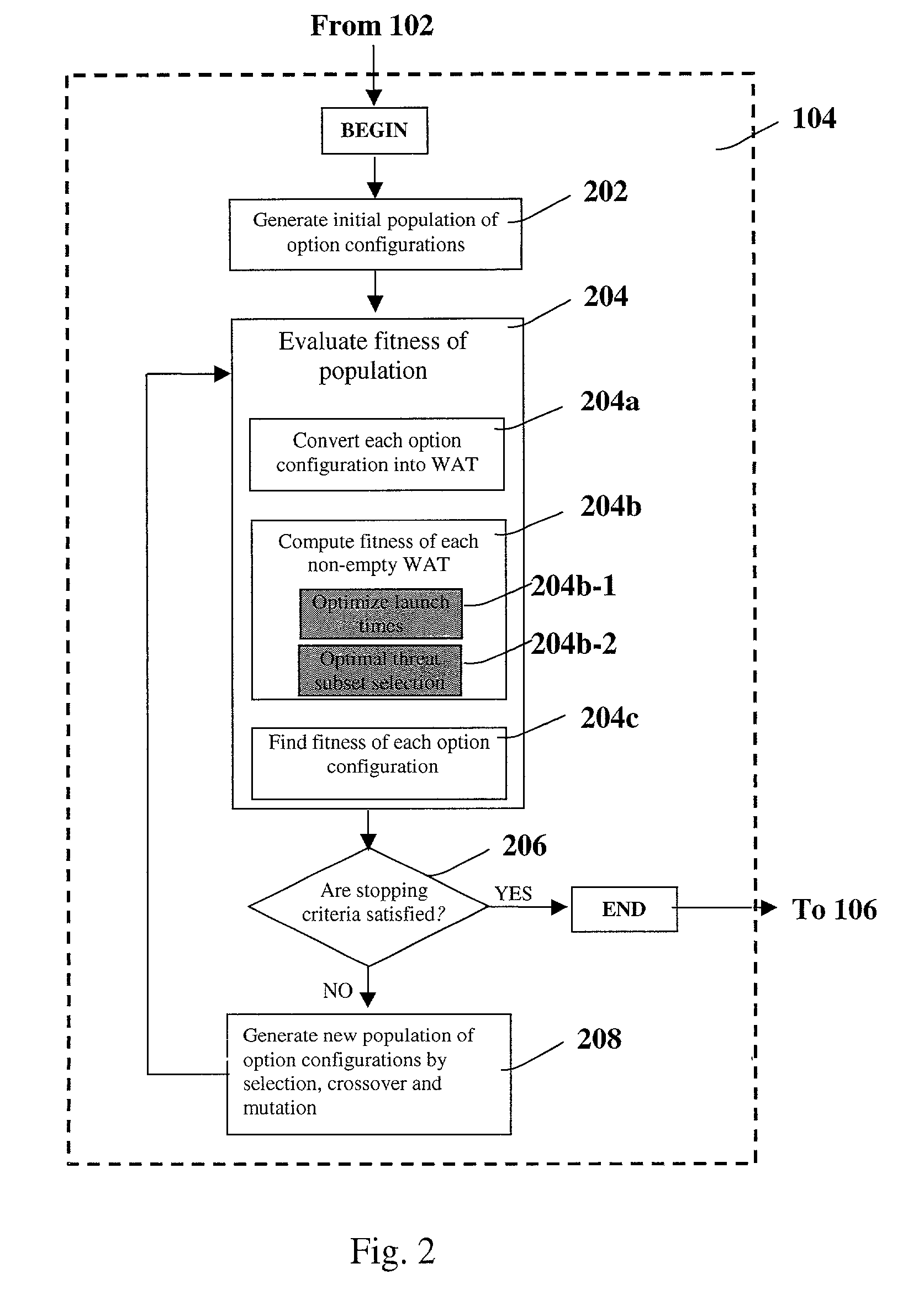
However, combination of the two steps introduces temporal dimension optimization into the asset allocation problem causing a combinatorial explosion in the solution space and resulting in a resource-constrained scheduling problem i.e., a Weapon Allocation and Scheduling problem (WASE).
This is a far-more computationally expensive problem than the static problem tackled in previous approaches.

Method used


Image

  • Method for automatic weapon allocation and scheduling against attacking threats
  • Method for automatic weapon allocation and scheduling against attacking threats
  • Method for automatic weapon allocation and scheduling against attacking threats

Examples


Embodiment Construction

[0023] Illustrative embodiments and exemplary applications will now be described with reference to the accompanying drawings to disclose the advantageous teachings of the present invention.

[0024] While the present invention is described herein with reference to illustrative embodiments for particular applications, it should be understood that the invention is not limited thereto. Those having ordinary skill in the art and access to the teachings provided herein will recognize additional modifications, applications, and embodiments within the scope thereof and additional fields in which the present invention would be of significant utility.

[0025] The present invention describes a method and system for automatically allocating and scheduling defensive weapons against attacking threats to maximize an engagement objective. In a typical battlefield situation at any time, there may be multiple threats headed towards valuable defended assets and multiple weapon systems available to counter...


PUM


Abstract

A system and method for automatic weapon allocation and scheduling of the present invention. The inventive method includes the steps of providing data with respect to threats, weapons, weapon allocation options; weapon allocation rules; and temporally dependent constraints with respect thereto; evaluating the data; and temporally allocating the weapons to the threats automatically in accordance with the evaluation. The invention computes the optimal pairing and the best time to deploy each weapon system against threat(s) it is paired with in arriving at the pairing. This results in an optimal assignment where weapon resource constraints are not exceeded and therefore guarantee availability of sufficient resources for engagement of every threat that is paired with a weapon system.

Description

[0001] 1. Field of the Invention[0002] The present invention relates to systems and methods for allocating and scheduling resources to satisfy one or more time critical objectives. More specifically, the present invention relates to systems and methods for automatically allocating and scheduling weapon system to threats such that a pre-specified battle-space engagement objective is optimized.[0003] 2. Description of the Related Art[0004] Previous approaches for automatically allocating and scheduling defensive weapons against attacking threats to maximize an engagement objective have only addressed the static target-weapon pairing problem which is to determine the optimal allocation of weapon systems to engage threats.[0005] While some of these approaches have used trial-intercept calculations to determine the window of engagement to determine a weapon system's effectiveness against a threat, they do not address the issue of when to deploy the weapon system against the threat in thi...

Claims


Application Information

Patent Timeline
Patent Type & Authority Applications(United States)
IPC IPC(8): F41G3/04F41H11/02
CPCF41G3/04F41H11/02
Inventor KHOSLA, DEEPAK
Owner RAYTHEON CO
Learn More