Dynamic rendering of ink strokes with transparency

a technology of ink strokes and transparency, applied in the direction of inking apparatus, separate processes, instruments, etc., can solve the problems of large processing power, imperfect solution, and ink not fully concealing the background behind

Inactive Publication Date: 2003-02-06
MICROSOFT TECH LICENSING LLC
View PDF0 Cites 47 Cited by
  • Summary
  • Abstract
  • Description
  • Claims
  • Application Information

AI Technical Summary

Problems solved by technology

Ink that is transparent means that the ink does not fully conceal the background behind it when displayed on a display or printed on a printer.
This is an imperfect solution, however, since in practice there is typically a short time interval between ink points, and repeatedly clearing and redrawing the screen uses massive amounts of processing power, not to mention causing the screen to flicker.
The problem with this is that the transparencies of the overlapping portion of ink segments are reduced in an unexpected and unintended manner.
The result is an unintentionally non-uniform ink stroke.
This is analogous to repeatedly making a glass window thicker, thereby making objects on the other side of the glass more difficult to see by making the window darker.

Method used


Image

  • Dynamic rendering of ink strokes with transparency
  • Dynamic rendering of ink strokes with transparency
  • Dynamic rendering of ink strokes with transparency

Examples


Embodiment Construction

[0033] Improved transparent ink rendering systems and methods are disclosed. The various embodiments of the invention are described in the following sections: General Purpose Computing Environment, Ink Rendering System, and Ink Smoothing.

[0034] General Purpose Computing Environment

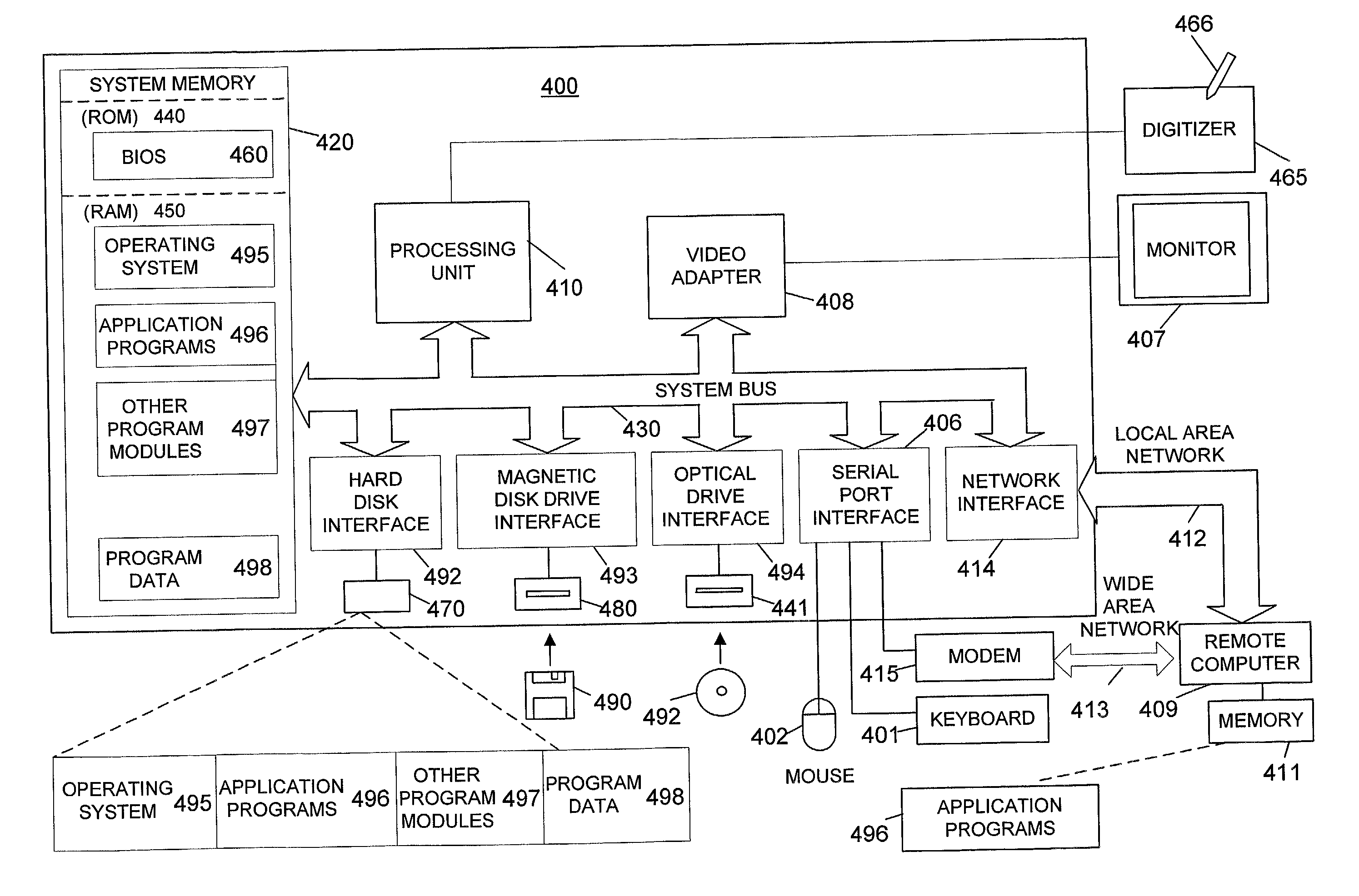
[0035] FIG. 4 illustrates a schematic diagram of an exemplary general-purpose digital computing environment that may be used to implement various aspects of the present invention. In FIG. 4, a computer 400 such as a personal computer includes a processing unit 410, a system memory 420, and / or a system bus 430 that couples various system components including the system memory to processing unit 410. System bus 430 may be any of several types of bus structures including a memory bus or memory controller, a peripheral bus, and a local bus using any of a variety of bus architectures. System memory 420 includes read only memory (ROM) 440 and random access memory (RAM) 450.

[0036] A basic input / output system 460 ...


PUM

PropertyMeasurementUnit
transparentaaaaaaaaaa

Abstract

Apparatus and methods for dynamically rendering transparent ink strokes, in some situations such that the rendered ink stroke has transparency similar to physical ink while it is being drawn. For example, the ink stroke may be dynamically rendered as a stroke having uniform transparency while it is being drawn. Only the new ink segment that has most recently been added to the stroke may be drawn, and areas of the new ink segment that overlap older segments of the ink stroke may be frozen, or excluded from being re-painted.

Description

[0001] This application is related to U.S. patent application Ser. No. TBD, entitled "Rendering Ink Strokes of Variable Width and Angle," attorney docket no. 03797.00129, filed simultaneously with the present application, and U.S. patent application Ser. No. TBD, entitled "Serial Storage of Ink and its Properties", attorney docket no. 03797.00132, filed May 11, 2001, both hereby incorporated by reference as to their entireties.[0002] The present invention is directed generally to rendering transparent digital ink, and more particularly to improved ways of rendering transparent digital ink dynamically.[0003] The term "digital ink" refers to one or more strokes that are recorded from a pointing device, such as a mouse, a stylus / pen on a digitizer tablet, or a stylus / pen on a display screen integrated with a digitizer tablet (e.g., a touch-sensitive display screen). As used herein, the term "ink" is shorthand for digital ink. Also, the term "pen" and "stylus" are used generically and i...

Claims


Application Information

Patent Timeline
Patent Type & Authority Applications(United States)
IPC IPC(8): B01D3/00B05C17/04B41J11/44B41L13/18B41L27/00C07C29/04G06F3/00G06F9/00G06F17/00G06T11/20G09G5/00
CPCG06T11/203
Inventor DRESEVIC, BODINKALLAY, MICHAEL
Owner MICROSOFT TECH LICENSING LLC
Why Eureka
Try Eureka