Systems and methods for correlating images in an image correlation system with reduced computational loads

a technology of image correlation and computational load, applied in image analysis, instruments, computing, etc., can solve the problems of reducing resolution or averaging techniques disclosed, and affecting the accuracy of image correlation functions

Inactive Publication Date: 2003-02-06
MITUTOYO CORP
View PDF10 Cites 80 Cited by
  • Summary
  • Abstract
  • Description
  • Claims
  • Application Information

AI Technical Summary

Problems solved by technology

However, in the above-described conventional image correlation systems, the computational loads required to determine the correlation function value over the entire image for each offset position are often extremely high.
However, unlike Hirooka et al. and Rosenfeld et al., the pixels used are at full resolution but do not represent the entire image to be compared.
However, at no time is any reduced representation of the images such as those disclosed in Hirooka et al., Rosenfeld et al. or Goshtasby et al. used.
However, the resolution reduction or averaging techniques disclosed in Hirooka et al. and Rosenfeld et al. are generally inapplicable to high spatial frequency images, such as speckle images, images resembling surface texture, and high density dot patterns and the like.
The coarsely-spaced search point techniques discussed in Musmann et al. are also generally inapplicable to such high-spatial-frequency images.
However, applying the coarsely-spaced search techniques disclosed in Musmann et al. to a correlation function having a substantial

Method used


Image

  • Systems and methods for correlating images in an image correlation system with reduced computational loads
  • Systems and methods for correlating images in an image correlation system with reduced computational loads
  • Systems and methods for correlating images in an image correlation system with reduced computational loads

Examples


Embodiment Construction

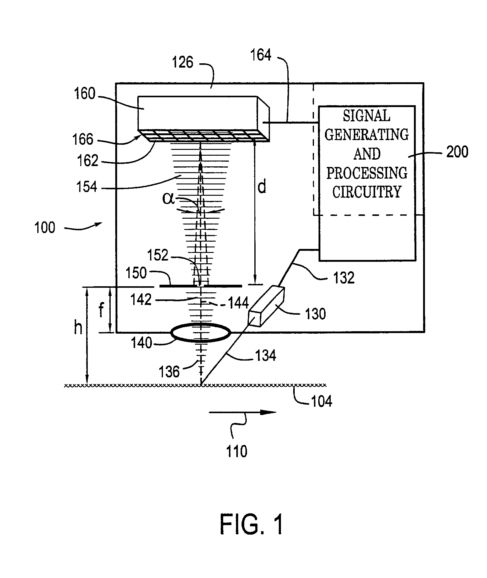
[0070] FIG. 1 is a block diagram of a correlation-image-based optical position transducer 100. It should be appreciated that, in the following detailed description, the systems and methods according to this invention will be described primarily relative to a speckle-image-based optical position transducer and corresponding methods and techniques. However, it should be appreciated that the systems and methods according to this invention are not limited to such speckle-image-based correlation systems and methods. Rather, the systems and methods according to this invention can be used with any known or later-developed system or method for determining a positional displacement or offset that uses any known or later developed type of correlation image, including texture images, high-density dot images and the like, so long as the correlation image has a high spatial frequency and / or is not truly repetitive. Thus, while the following detailed description of the exemplary embodiments may r...


PUM


Abstract

After one or both of a pair of images are obtained, an auto-correlation function for one of those images is generated to determine a smear amount and possibly a smear direction. The smear amount and direction are used to identify potential locations of a peak portion of the correlation function between the pair of images. The pair of images is then correlated only at offset positions corresponding to the one or more of the potential peak locations. In some embodiments, the pair of images is correlated according to a sparse set of image correlation function value points around the potential peak locations. In other embodiments, the pair of images is correlated at a dense set of correlation function value points around the potential peak locations. The correlation function values of these correlation function value points are then analyzed to determine the offset position of the true correlation function peak.

Description

[0001] 1. Field of Invention[0002] This invention is directed to image correlation systems.[0003] 2. Description of Related Art[0004] Various known devices use images acquired by a sensor array, and correlation between images acquired by the sensor array, to determine deformations and / or displacements. For example, one class of such devices is based on acquiring a speckle image generated by illuminating an optically rough surface with a light source. Generally, the light source is a coherent light source, such as a laser-generating light source. Such laser-generating light sources include a laser, laser diode and the like. After the optically rough surface is illuminated by the light source, the light scattered from the optically rough surface is imaged onto an optical sensor. The optical sensor can be a charge-couple device (CCD), a semi-conductor image sensor array, such as a CMOS image sensor array, or the like.[0005] Prior to displacing or deforming the optically rough surface, ...

Claims


Application Information

Patent Timeline
IPC IPC(8): G06K9/64G06T7/00
CPCG06K9/6203G06T7/001G06T7/0026G06T7/0044G06T7/32G06T7/74G06V10/7515
Inventor NAHUM, MICHAEL
Owner MITUTOYO CORP
Why Eureka
Try Eureka