
Visual and audio system for theaters

Inactive Publication Date: 2003-02-27
CHOI HAE YONG
View PDF0 Cites 132 Cited by
  • Summary
  • Abstract
  • Description
  • Claims
  • Application Information

AI Technical Summary

Problems solved by technology

Although it is possible to view stereoscopic images under the condition in which both the right and left images have a high brightness, this has not been accomplished due to the above-mentioned degraded brightness.
However, such an image planarization process becomes a main cause of deteriorating a desired visual presence.
For this reason, the range of a viewing field to feel the visual presence is narrow, so that viewers cannot perceive a satisfactory the visual presence.
For this reason, the screen is usable only in a dark room, and thus viewers do not see the desired image depth.
However, it is impossible to view these contents at a screen brightness adopted in typical theaters because the screen is too dark(the screen brightness is too low).
At the low screen brightness, it is impossible to obtain the satisfactory image depth and the desired color reproduction.
For this reason, it is impossible to clearly display images.
However, there is no way except intensifying the light source of the projector.
Particularly, when the distance between the screen and the seats is short, like in a small theater, the resolution of the screen is deteriorated so that digital images with the visual presence cannot be applied to the small theaters.
For this reason, the surface of the screen becomes rough, and the resolution and reflectivity of the screen are deteriorated, so that the brightness of the screen is lowered.
When the reflectivity of the screen surface S is less than 5%, the quantity of reflected light is very small and thus optical function of the screen required in the present invention is poor.
Raising the reflectivity the screen surface, however, does not always ensure improved screen functions.
However, such a spherical screen shape does not necessarily ensure a desired complete image viewing.

Method used


Image

  • Visual and audio system for theaters
  • Visual and audio system for theaters
  • Visual and audio system for theaters

Examples


Embodiment Construction

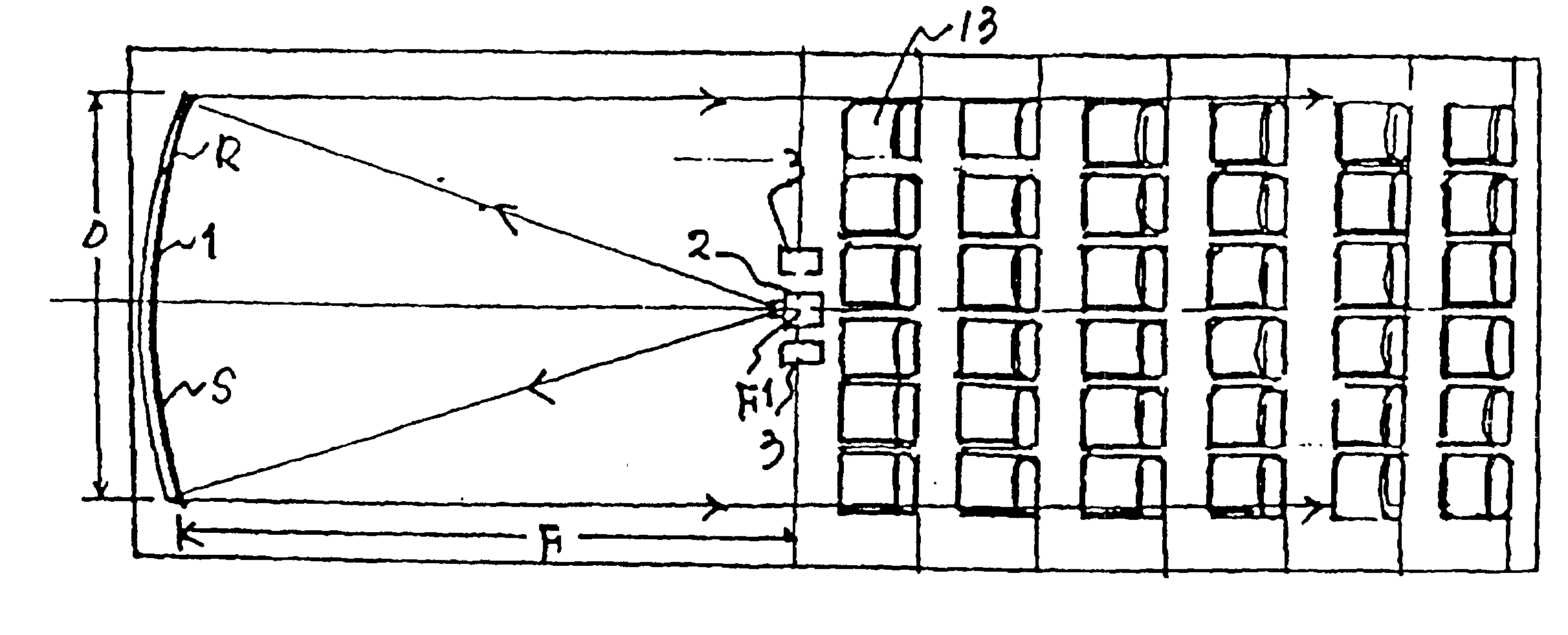
[0073] 1) Size of the spherical screen 1: 12.4 ft (376 cm) (horizontal).times.5.29 ft (160 cm)(vertical) (2.35:1), the screen size: diagonal.apprxeq.185"

[0074] 2) Surface reflectivity S of the spherical screen 1: 20% (20 Gains)

[0075] 3) Projection distance F when an image from the projector 2 is projected onto the spherical screen 1 having a diagonal size of 185": 19.8 ft (6 m)

[0076] 4) Curvature Radius R of the spherical screen 1: 39.6 ft (12 m)(1,2000R)

[0077] 5) Distance F1 between the spherical screen 1 and the projector 2: 19.8 ft (6 m)

[0078] 6) Distance between the spherical screen 1 and each central speaker 3: 19.8 ft (6 m)

[0079] 7) Horizontal length D along which the seats 13 are horizontally arranged: 12.4 ft (376 cm)

[0080] 8) Vertical length D1 along which the seats 13 are vertically arranged: 5.29 ft (160 cm)

[0081] The screen ratio typically adopted in a general theater is 2.35:1. Therefore, the spherical screen 1 is a large-size screen having a diagonal length as long as ...


PUM


Abstract

Disclosed is a visual and audio system for theaters including a spherical screen having a desired radius of curvature while having a surface reflectivity of 5-50%, and a projector located at a focal point of the spherical screen. The curvature radius of the spherical screen corresponds to the projection distance of the projector. The image projected from the projector at the focal point of the spherical screen is reflected from the spherical screen in a horizontal direction. Accordingly, viewers can view images projected on the screen corresponding to 5-50 times the brightness of conventional cases. Central speakers are arranged at the focal point of the spherical screen, so that viewers perceive the sound effect as coming directly from the spherical screen. This visual and audio system can be effectively used in theaters for stereoscopic movies, theaters for high resolution images, and theaters for viewing of images at a higher brightness such as theaters for sports broadcasts, and restaurant theaters, etc.

Description

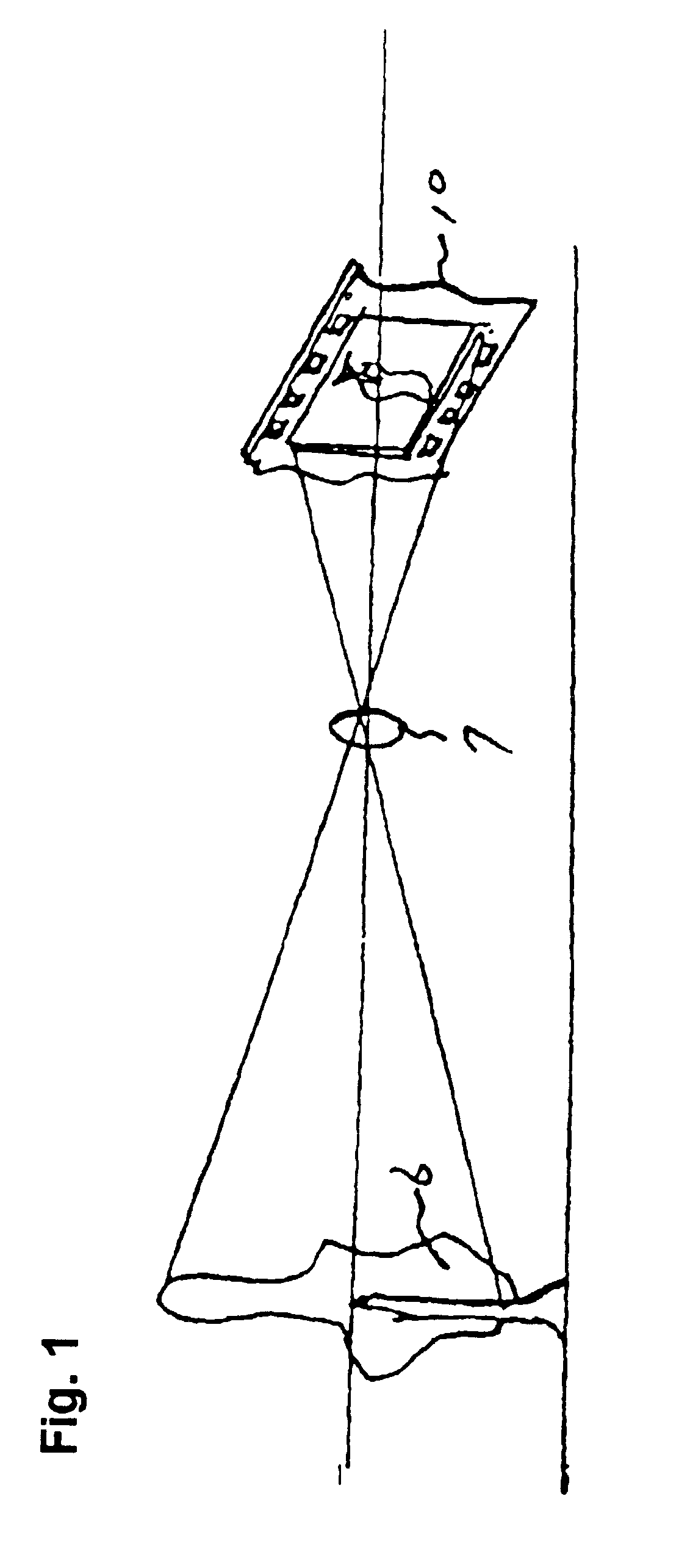
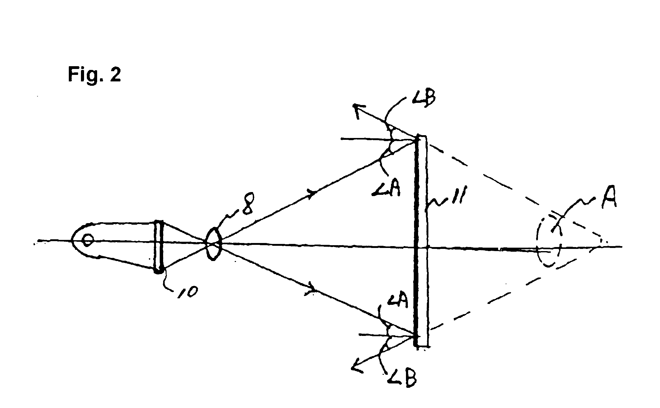
[0001] 1. Field of the Invention[0002] The present invention relates to a visual and audio system for theaters, and more particularly to a visual and audio system for theaters which can achieve a remarkable improvement in brightness, visual presence, and resolution, while extending the field of visual presence to the entire screen area, and allowing viewers to experience a sound effect coming directly from the screen.[0003] 2. Description of the Related Art[0004] Conventional visual and audio systems for theaters include a projector, a planar screen, and an audio system installed behind the planer screen.[0005] Referring to FIG. 11, a conventional stereoscopic visual and audio system is illustrated. As shown in FIG. 11, the conventional stereoscopic visual and audio system includes a pair of projectors 2, polarizers 4 symmetrically arranged at the front of projection lenses respectively attached in the projectors 2 while defining a certain angle therebetween, and a planar screen 11....

Claims


Application Information

Patent Timeline
IPC IPC(8): A63J5/04A63J13/00A63J25/00A63J99/00G03B21/00G03B21/56H04N5/74H04R1/34H04S5/02
CPCG03B21/56G03B21/00
Inventor CHOI, HAE-YONG
Owner CHOI HAE YONG
Learn More