Projection optical system

a technology of optical system and projection lens, which is applied in the direction of mirrors, instruments, mountings, etc., can solve the problems of obstructing the viewing of images, difficult to view images, and inability to focus

Active Publication Date: 2008-08-14
KONICA MINOLTA OPTO
View PDF12 Cites 26 Cited by
  • Summary
  • Abstract
  • Description
  • Claims
  • Application Information

AI Technical Summary

Benefits of technology

[0012]In view of the conventionally encountered inconveniences mentioned above, it is an object of the present invention to provide a compact, high-performance projection optical system that produces, in short-distance front projection, a

Problems solved by technology

Thus, in cases where, for example, the projection optical system is set up on a desk, as the projection distance increases, the image moves upward over so long a distance that it is difficult to view the image.
Inconveniently, however, including two or more curved-surfaced mirrors, the projection optical systems proposed there have a large dimension

Method used


Image

  • Projection optical system
  • Projection optical system
  • Projection optical system

Examples


examples

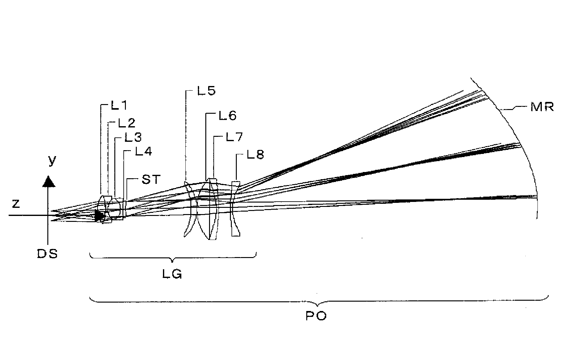
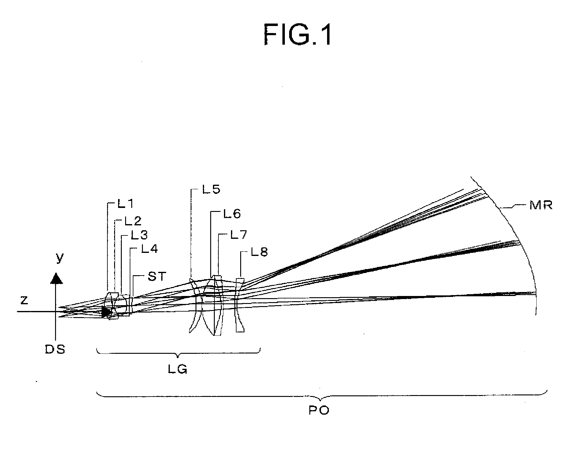
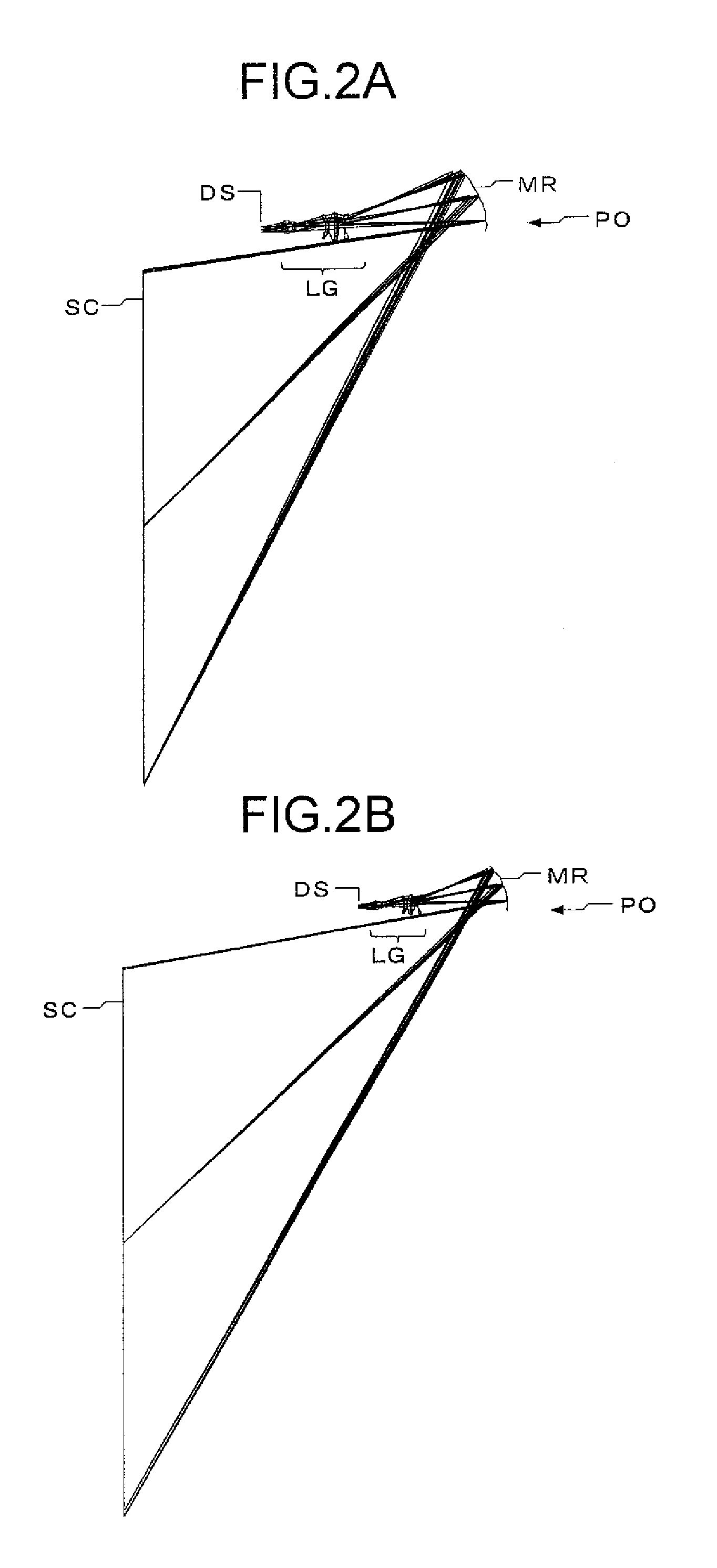
[0132]Hereinafter, practical examples of projection optical systems etc. according to the invention will be presented more specifically with reference to their construction data etc. Examples 1 to 3 presented below are numerical examples corresponding to the first to third embodiments, respectively, described above, and thus the optical construction diagrams, optical path diagrams, etc. (FIGS. 1, 2A, and 2B, FIGS. 5, 6A, and 6B, and FIGS. 9, 10A, and 10B) showing the first to third embodiments also show the optical arrangement, projection optical path, etc. of the corresponding ones of Examples 1 to 3.

[0133]Tables 1 to 5, Tables 6 to 10, and Tables 11 to 16 show the construction data of Examples 1 to 3, respectively. Table 17 shows, for each example, the data corresponding to and related to the relevant conditional formulae (βx represents the image magnification in the direction of the longer sides of the image-display area, and βy represents the image magnification in the direction...


PUM


Abstract

A projection optical system that receives light from a display element to project an image displayed by the display element onto a screen with enlargement at a varying magnification achieved by varying the projection distance to the screen has: a refractive optical system composed of one or more refractive lenses and having a positive optical power; and a concave-surfaced mirror disposed to the screen side of the refractive optical system and having a plane-symmetric reflective surface. The projection optical system includes at least one optical element designed to be movable for focusing. The projection optical system forms an intermediate image between the refractive optical system and the concave-surfaced mirror. Moreover, a prescribed conditional formula is fulfilled.

Description

[0001]This application is based on Japanese Patent Application No. 2007-33038 filed on Feb. 14, 2007 and Japanese Patent Application No. 2008-25615 filed on Feb. 5, 2008, the contents of which are hereby incorporated by reference.BACKGROUND OF THE INVENTION[0002]1. Field of the Invention[0003]The present invention relates to a projection optical system, and more particularly to a projection optical system for short-distance front projection whereby, for example, a large image is projected from a position close to a screen.[0004]2. Description of Related Art[0005]In recent years, projectors employing a digital micromirror device or LCD (liquid crystal display) have been becoming increasingly popular, and various types of them have been proposed. For example, as projection optical systems adopting oblique projection to offer a short projection distance, Patent Document 1 listed below proposes a type in which the last surface is a convex-surfaced mirror; on the other hand, Patent Docum...

Claims


Application Information

Patent Timeline
IPC IPC(8): G02B17/00
CPCG02B17/08G03B21/28G03B21/10
Inventor OHZAWA, SOH
Owner KONICA MINOLTA OPTO
Why Eureka
Try Eureka