Display apparatus, display method, and display system

Inactive Publication Date: 2010-04-15
SONY CORP
View PDF6 Cites 24 Cited by
  • Summary
  • Abstract
  • Description
  • Claims
  • Application Information

AI Technical Summary

Benefits of technology

[0019]According to the display apparatus, the display method, and the display system according to the above embodiments of the invention, the video image display size and the information indicating the magnitude of disparity are used to ad

Problems solved by technology

When the apparatus is a projector, however, the conditions under which users install the projector differ from one another in many cases and the magnitude of disparity greatly depends on the size of th

Method used


Image

  • Display apparatus, display method, and display system
  • Display apparatus, display method, and display system
  • Display apparatus, display method, and display system

Examples


first embodiment

Exemplary Configuration of Display Apparatus

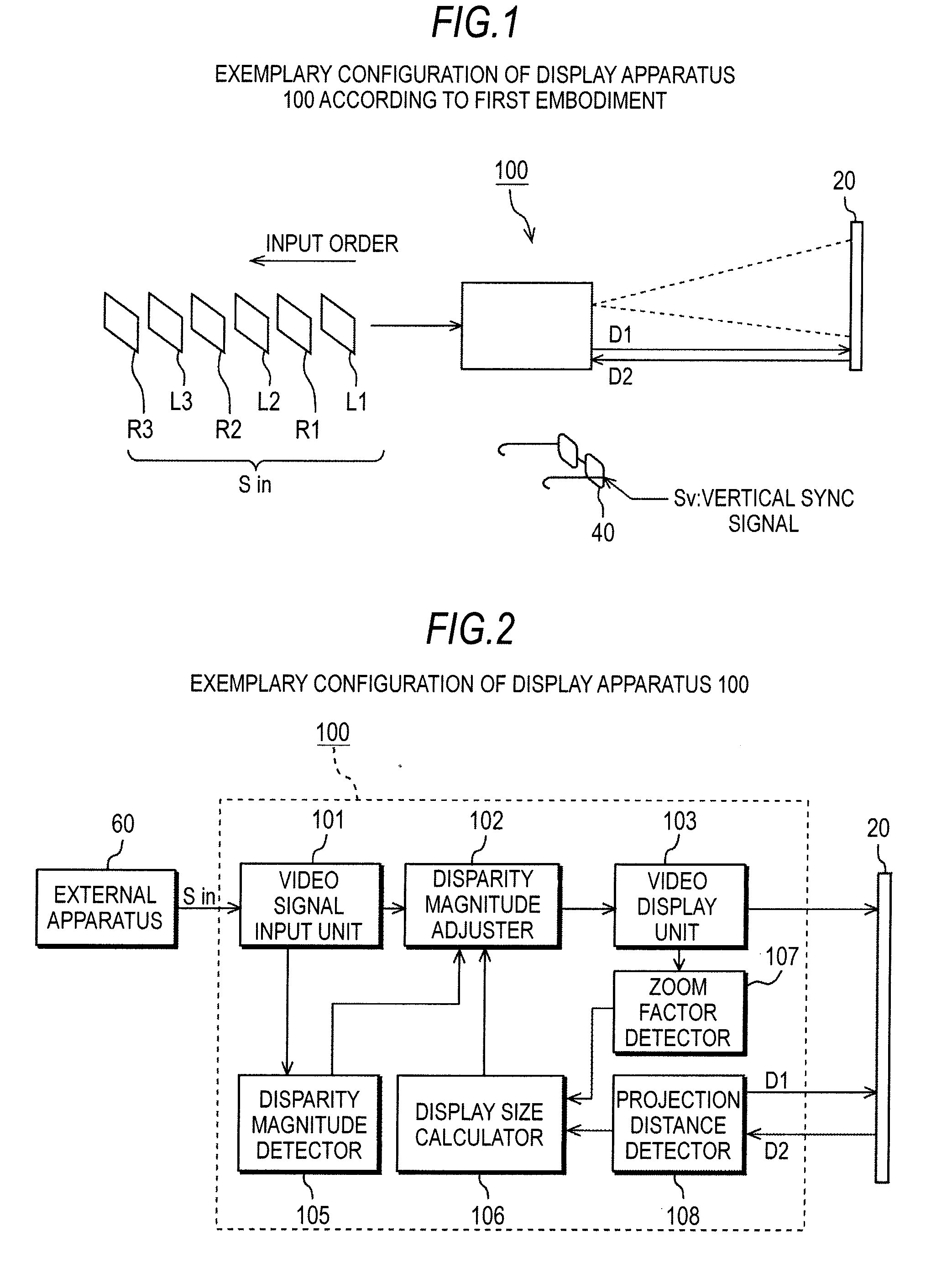
[0039]A display apparatus according to an embodiment of the invention will be described below with reference to the drawings. FIG. 1 is a descriptive diagram showing an exemplary configuration of a display apparatus 100 according to a first embodiment. The display apparatus 100 shown in FIG. 1 can be used, for example, in a front-projection projector that displays three-dimensional stereoscopic video images.

[0040]As shown in FIG. 1, the display apparatus 100 receives a video signal Sin. The video signal Sin is formed of left-eye image signals L1, L2, and L3, right-eye image signals R1, R2, and R3, and information indicating the magnitude of disparity (not shown). The display apparatus 100 receives the left-eye image signals and the right-eye image signals multiplexed in the following order by using time division multiplexing: the left-eye image signal L1, the right-eye image signal R1, the left-eye image signal L2, the right-eye image sign...

second embodiment

When Two Display Apparatus are Used

No. 1

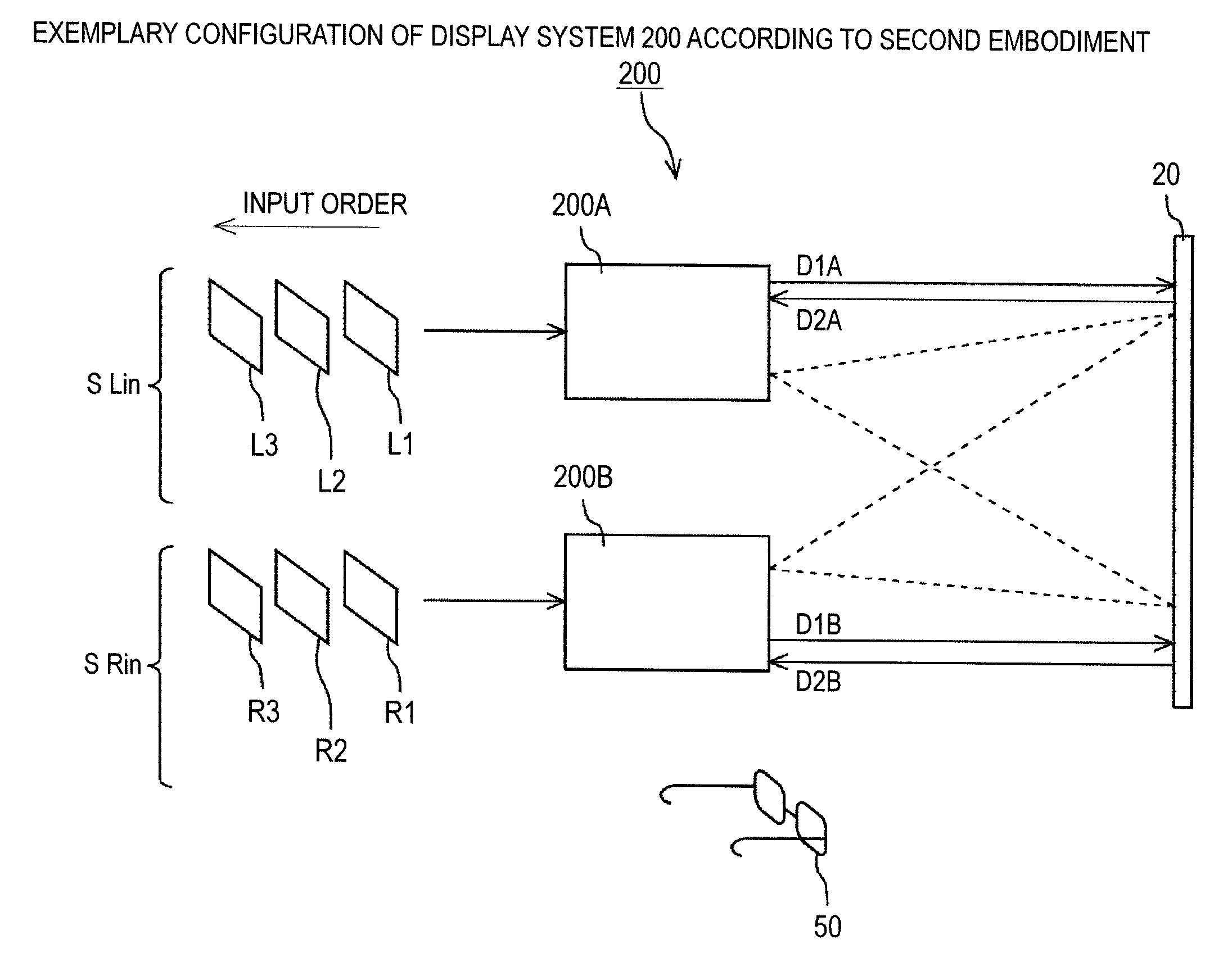
[0088]FIG. 8 is a descriptive diagram showing an exemplary configuration of a display system 200 according to a second embodiment, and FIG. 9 is a block diagram of the display system 200. The display system 200 shown in FIGS. 8 and 9 uses two display apparatus 100 according to the first embodiment described above to display left and right disparity video images.

[0089]As shown in FIGS. 8 and 9, the display system 200 includes a first display apparatus that displays left-eye video images (hereinafter referred to as a display apparatus 200A) and a second display apparatus that displays right-eye video images (hereinafter referred to as a display apparatus 200B).

[0090]The display apparatus 200A includes a first disparity magnitude adjuster (hereinafter referred to as a disparity magnitude adjuster 202A), a first video display unit (hereinafter referred to as a video display unit 203A), a first disparity magnitude detector (hereinafter referred to ...

third embodiment

When Two Display Apparatus are Used

No. 2

[0120]FIG. 11 is a descriptive diagram showing an exemplary configuration of a display system 300 according to a third embodiment, and FIG. 12 is a block diagram of the display system 300. The display system 300 shown in FIGS. 11 and 12 is similar to the display system 200 according to the second embodiment described above but has a function of creating information indicating the magnitude of disparity. Since the portions having the same names and reference characters as those in the second embodiment have the same functions, no redundant description will be made.

[0121]As shown in FIGS. 11 and 12, the display system 300 includes a first display apparatus that displays left-eye video images (hereinafter referred to as a display apparatus 300A) and a second display apparatus that displays right-eye video images (hereinafter referred to as a display apparatus 300B).

[0122]The display apparatus 300A includes a first disparity magnitude adjuster (he...


PUM


Abstract

A display apparatus includes: a video display unit that converts a video signal containing information indicating the magnitude of disparity between left-eye and right-eye video images into video images and displays the video images on a screen; a projection distance detector that detects a projection distance that is the distance between the video display unit and the screen; a display size calculator that calculates the size of the video images displayed on the screen using the projection distance detected by the projection distance detector; a disparity magnitude detector that detects the information indicating the magnitude of disparity from the video signal; and a disparity magnitude adjuster that adjusts the magnitude of disparity using the size of the video images displayed on the screen and the information indicating the magnitude of disparity detected by the disparity magnitude detector.

Description

BACKGROUND OF THE INVENTION[0001]1. Field of the Invention[0002]The present invention relates to a display apparatus, a display method, and a display system useable in a front-projection projector that displays three-dimensional stereoscopic video images.[0003]Specifically, information indicating the magnitude of disparity between left-eye and right-eye video images and the video image display size determined from a projection distance are used to adjust the magnitude of disparity, whereby the magnitude of disparity can be optimized and automatically adjusted.[0004]2. Description of the Related Art[0005]In recent years, front-projection projectors have been advancing in terms of resolution and image quality, and quite a few users have such projectors installed in their living rooms and convert them into home theaters. Further, increase in the number of movie theaters with facilities capable of showing stereoscopic video content using left and right disparity video images may lead to...

Claims


Application Information

Patent Timeline
IPC IPC(8): H04N13/04H04N13/363
CPCH04N13/0022H04N13/0497H04N13/0459H04N13/363H04N13/128H04N13/398
Inventor YOSHIFUJI, KAZUNARIOHASHI, ISAOOOI, TAKUYATAKAHASHI, SHUICHI
Owner SONY CORP
Why Eureka
Try Eureka