Optical information medium

a technology of optical information and information medium, applied in the direction of mechanical recording, flat record carrier container, instruments, etc., can solve the problems of deteriorating shock resistance, prone to warpage of discs, prone to flaking of adhesive surfaces,

Inactive Publication Date: 2003-02-27
TAIYO YUDEN KK
View PDF11 Cites 15 Cited by
  • Summary
  • Abstract
  • Description
  • Claims
  • Application Information

AI Technical Summary

Benefits of technology

[0014] Since the thickness of the adhesive 11 ranges 10 to 80 .mu.m, the coating layer of the UV curing resin adhesive for instance shows a sufficient viscosity, and even if bubbles are produced when the main surface of other disc contacts the coating layer, the viscose adhesive of the coating layer flows to fill up the bubble holes. Even if the viscose adhesive of the coating layer is cured by the irradiation of the UV rays while bubbles remain therein, the stress generated based on these bubbles can be reduced by the deformation caused by the plasticity and elasticity of the resin, thereby reducing the influence upon the recording layer. If the thickness of the adhesive 11 is less than 10 .mu.m, the bubbles can not be filled up by the deformation of the adhesive 11. On the other hand, if the thickness of the adhesive 11 exceeds 80 .mu.m, the curing speed of the adhesive 11 reduces so that the adhesive 11 is liable to be non-curable.
[0027] The boundary of the non-bonding area m is not always to be circular which is disposed at a fix range from the centers of the discs 1 and 5 but may be indefinite. That is, the boundary of the non-bonding area m may be eccentric relative to the centers of the discs 1 and 5 or the boundary of the non-bonding area m may be of different shape. In such a manner, the maximum amplitude Q of a mechanical resonance frequency f.sub.o may be reduced, so that the oscillation of the optical information medium can be reduced at the high speed revolution thereof.

Problems solved by technology

In such a WORM optical information medium, if the optical recording layer of the disc is coated with an adhesive such as a reactive curing resin by a spin coating process or a screen printing, etc., and two discs are bonded to each other by this adhesive, residual stress is generated in the jointing boundary between the different materials, whereby the discs are liable to warp and the adhesive surface is liable to flake owing to the warpage of the discs.
Further, there occurs a problem that when a shock is applied to the discs, the discs are liable to flake, thereby deteriorate a shock resistance.
Particularly, the flaking is liable to occur at the edges of two discs, which causes a problem of brittleness against the shock on the edges.
Still further, since the adhesion between two discs is deteriorated, the moisture in the air is liable to enter the discs, which causes a problem of deterioration of the layer with moisture.
If a reaction-sensitive resin is employed as an adhesive layer, the shrinkage involved in the curing occurs, and the stress generated thereby influences the recording layer, thereby distorting the recording layer.
The variation rate exceeds 30%, thereby obstructing the record and reproduction of the information.
When two discs are laid on top of the other, bubbles are liable to enter between two discs, and hence the stress is liable to occur by bubbles at the time of bonding the discs, and the magnitude of the stress increases.
A vacuum degassing apparatus is employed to prevent bubbles from entering the adhesive layer when two discs are bonded to each other, which makes the apparatus large-scaled, and hence increasing the operating process, which causes a problem of deterioration of productivity.

Method used


Image

  • Optical information medium
  • Optical information medium
  • Optical information medium

Examples


first embodiment

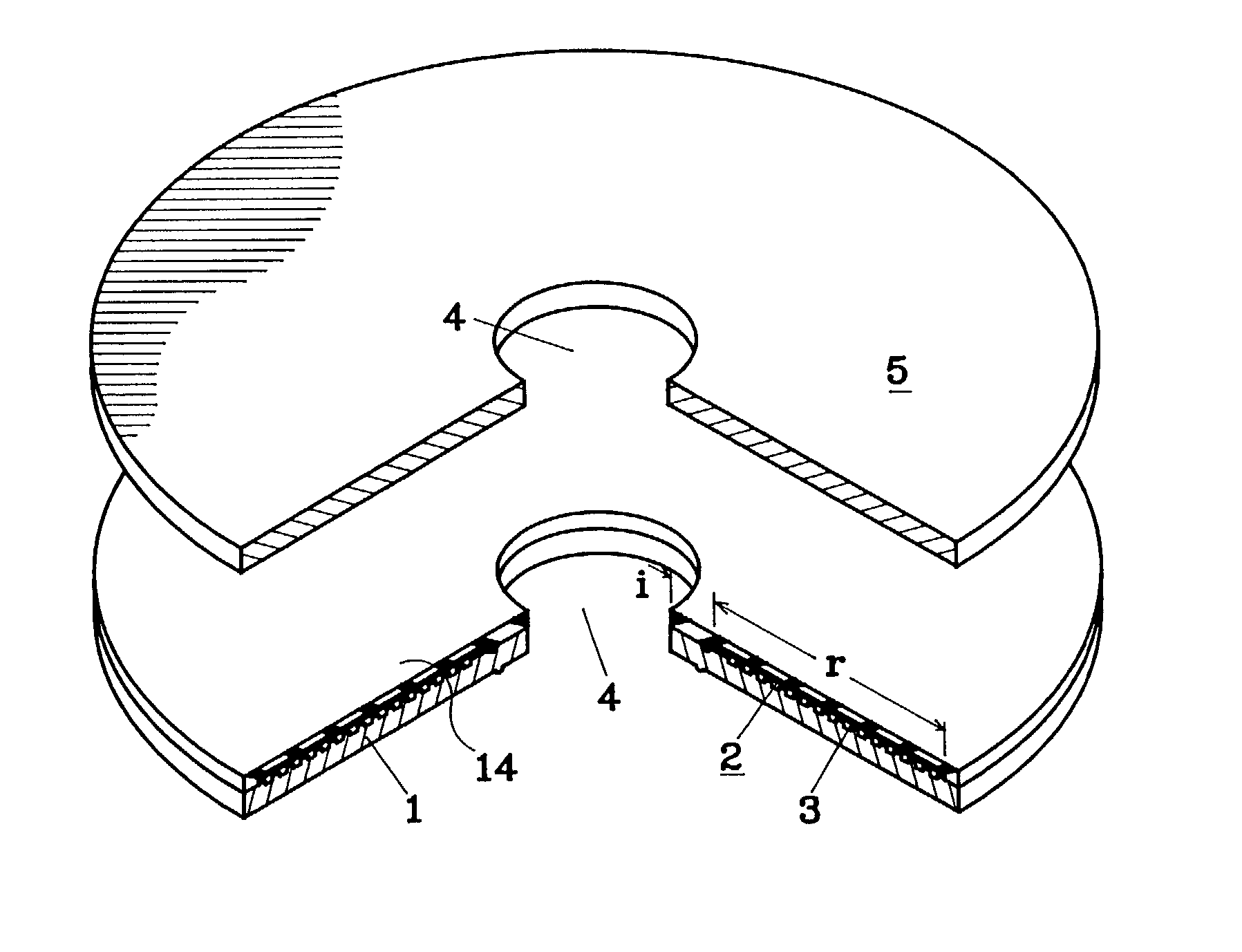
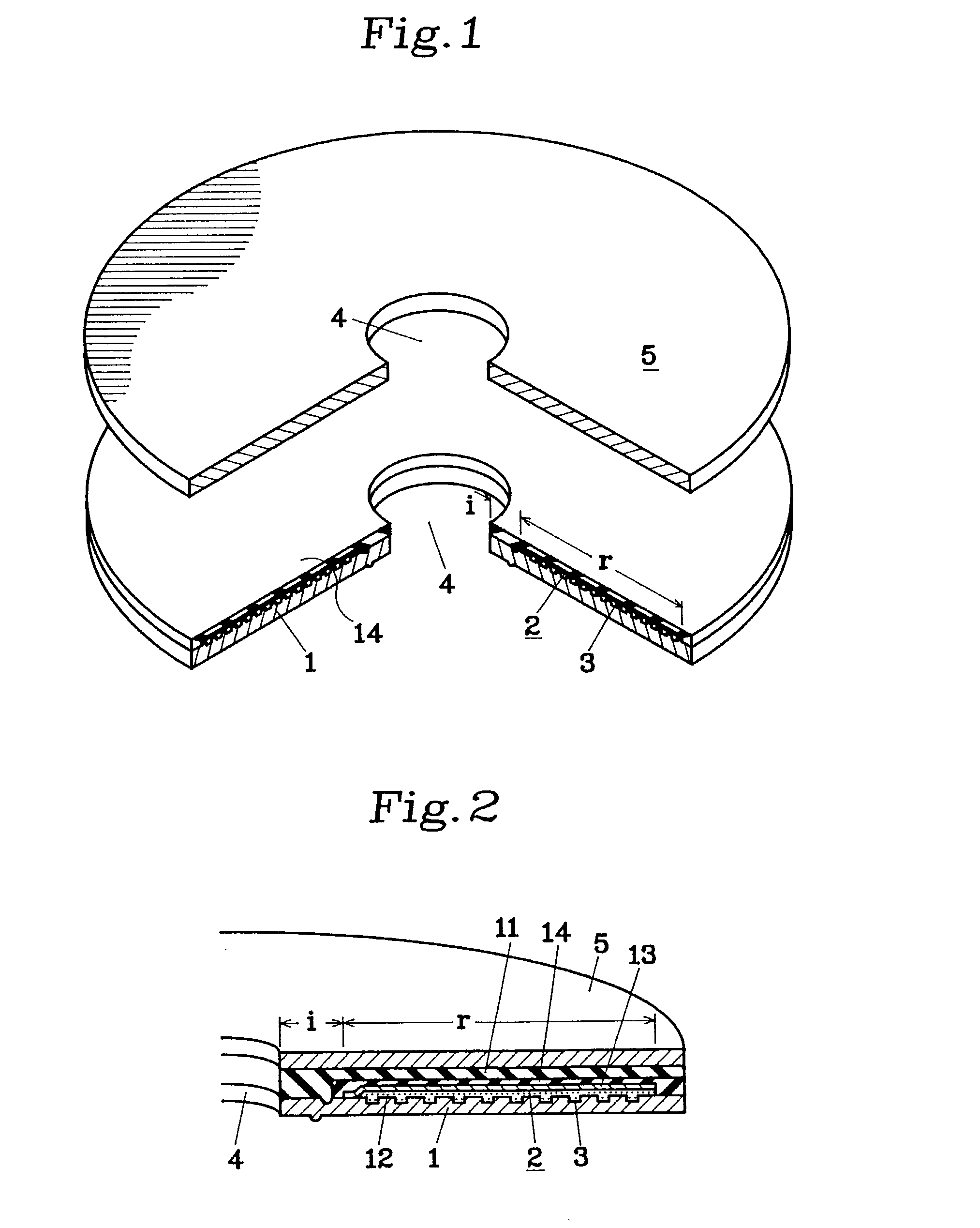
[0064] The first embodiment relates to the case where the disc 1 having the tracking guide 3 and the information recording layer 2 which are respectively formed on the information recording area r on the transparent substrate, and the disc 5 having no information recording layer are bonded to each other. In this case, the recording and reproduction can be made at one surface of the disc 1 or disc 5. The disc 5 may be formed of the one having no transparency or the colored one for maintaining the light resistance or the one having an area in which characters and patterns can be written in the surface thereof.

[0065] Meanwhile, two pieces of discs 1 each having the tracking guide 3 and information recording layer 2 provided at the information recording area r on the transparent substrate are prepared, and the information recording layers 2 oppose each other to form the optical information medium capable of recording and reproducing at both surfaces thereof. As the disc 5 to be used in ...

fourth embodiment

[0073] As mentioned above, the resistivity of friction between the discs 1 and 5 is weak particularly between the dye film and metal film, and hence if the dye film remains on the edge of the disc 1, the flake between the dye film and metal film is liable to occur at that portion. Compared with this, the sufficient resistivity of friction can be obtained between the discs 1 and 5, between the metal films, and between the disc 1 and metal film. Accordingly, it is necessary not to form the dye film for forming the optical recording layer 12 at the aforementioned marginal portions. In other words, if the dye film is not present at the marginal portion, the adhesion and hermeticity can be secured even if there is a metal film for forming the reflecting layer 13. As an optical information medium a WORM optical information medium having one surface record / reproduction structure formed by bonding two surfaces of discs will be now described with reference to FIGS. 6 and 5. The structure of...

fifth embodiment

[0077] FIG. 7 shows an optical information medium according to the invention. In FIG. 7(a), the groove 7 is defined in only the outer peripheral edge of the information recording layer 2, and the groove 6 is not defined in the disc 1. In FIGS. 7(b) to (d), the grooves 6 and 6 are defined in the main surfaces of the discs 1 and 5 at the position close to the inner peripheral surface rather than the outer peripheral surface, and they do not appear on the outer peripheral surfaces of the discs 1 and 5. Accordingly, in the optical information medium shown in FIGS. 7(b) to (d), it appears as if it had no outer peripheral surfaces like the optical information medium having no grooves 6 and 6 in external appearance. The grooves 6 and 6 of the discs 1 and 5 shown in FIG. 7(b) are rectangular. The grooves 6 and 6 of the discs 1 and 5 shown in FIG. 7(c) are semi-circular. The grooves 6 and 6 of the discs 1 and 5 shown in FIG. 7(d) have trapezoidal shape each having an inclination at one surfa...


PUM

PropertyMeasurementUnit
thicknessaaaaaaaaaa
shrinkage rateaaaaaaaaaa
widthaaaaaaaaaa

Abstract

An optical information medium comprises a pair of discs which are bonded to each other, an optical recording layer provided on at least one of the discs, a reflecting layer formed on an upper side of the optical recording layer. The optical information medium further includes an adhesive for bonding the pair of discs provided on the reflecting layer, wherein the adhesive has a thickness ranging from 10 to 80 mum. A protecting layer is provided on the upper side of the reflecting layer wherein the pair of discs may be bonded by the protecting layer. The optical recording layer, reflecting layer and protecting layer may be directly sequentially provided on the disc but another substrate layer may be inserted between these layers. There is employed, as the adhesive, that including a reactive curing resin or a hot melt material, and it is preferable that the shrinkage rate of the adhesive be less than 15%.

Description

[0001] 1. Field of the Invention[0002] The present invention relates to an optical information medium comprising one disc formed of a transparent substrate and having an optical recording layer and an reflecting layer at least on one surface thereof and another disc which is bonded to one disc by an adhesive.[0003] 2. Prior Art[0004] A digital video disc (DVD) capable of recording and reproducing information with high-density has been now put into practical use associated with the recent development and practical utilization of a laser having a short wavelength. The optical information medium of this type can adopt a structure for bonding two pieces of discs.[0005] A read-only optical information medium having such a structure for bonding two surfaces of discs has a center hole at the center thereof and a clamping area at the outside thereof. A pair of discs which are bonded to each other include at least one transparent substrate comprising at one surface thereof, an information re...

Claims


Application Information

Patent Timeline
Patent Type & Authority Applications(United States)
IPC IPC(8): G11B7/24G11B7/247G11B23/00G11B23/40
CPCG11B7/24024G11B7/2467G11B7/2472G11B7/2531G11B7/2533G11B7/2534G11B7/2535G11B7/256G11B7/2585G11B7/2595G11B23/0042G11B23/40
Inventor FUJII, TORUTOMIZAWA, YUJIHAMADA, EMIKO
Owner TAIYO YUDEN KK
Why Eureka
Try Eureka