Knife-positioning washer for piloted router bit

Inactive Publication Date: 2003-02-27
GOLDING THOMAS H III
View PDF0 Cites 16 Cited by
  • Summary
  • Abstract
  • Description
  • Claims
  • Application Information

AI Technical Summary

Benefits of technology

0003] It is of particular importance in two-knife bits to have both knives be properly positioned, otherwise a single knife will wear much quicker than the other. It is also desirable to be able to change knives without removing the bit from the chuck to save time. For those bits having a front bearing, removal of the bit from the router is even more time-consuming.
0004] There is therefore, a need for an insert router bit which allows replacement of worn knives quickly and wi

Problems solved by technology

The knives are subject to wear and must be periodically replaced when they become dull.
For tho

Method used


Image

  • Knife-positioning washer for piloted router bit
  • Knife-positioning washer for piloted router bit

Examples


Embodiment Construction

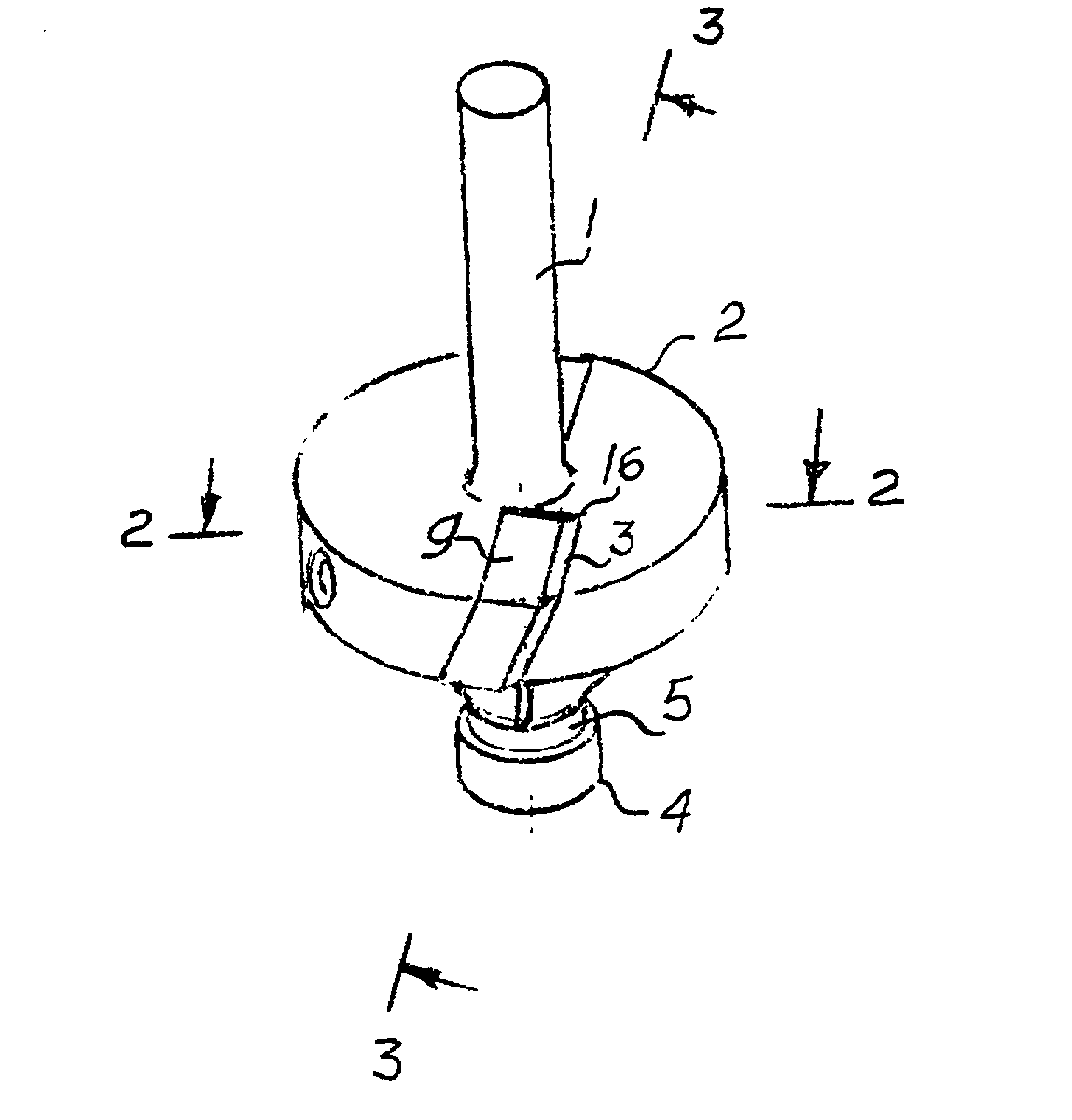
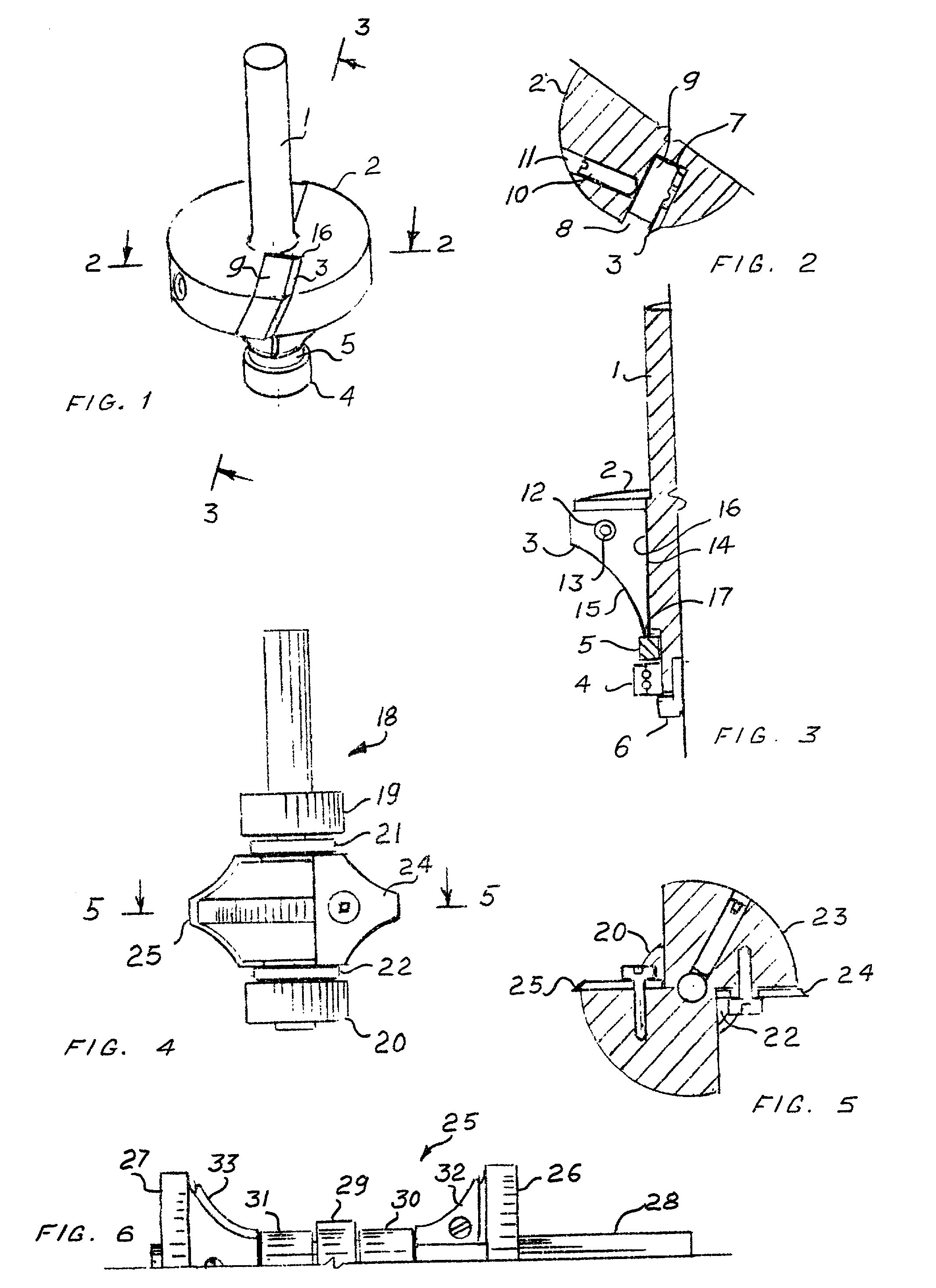
[0012] Referring now to the drawing, there is shown in FIG. 1, a first piloted router bit which comprises a shank 1 for attachment to the chuck of a router, a tool section or tool body 2 mounting a pair of knives 3 and a rotating bearing 4 at the distal end of the tool body coaxial with it and with the shank. A spacer such as a washer 5 is interposed between the distal end of the tool section and the bearing 4. The washer and the bearing 4 are retained by an axial screw 6 at the base of the tool. Each knife 3 is held against a slanted, radial mounting surface 7 of a slot 8 cut into the tool section. A clamping plate 9 holds the knife 3 against the mounting surface 7. The clamping plate is pressed by a screw 10 mounted in a threaded hole 11 bored through the tool section. One or more holes 12 in the blade are engaged by nibs 13 projecting from the clamping plate. The diameter of the knife hole 12 is larger than the diameter of the nib 13 allowing the blade to be adjustably positioned...


PUM

PropertyMeasurementUnit
Diameteraaaaaaaaaa
Lengthaaaaaaaaaa
Radiusaaaaaaaaaa

Abstract

In a piloted router bit, the knife is conveniently aligned by positioning one of its edges against a spacer or washer interposed between the tool section of the router bit and its rotating bearing.

Description

FIELD Of THE INVENTION[0001] This invention relates to tooling for machining and more particularly to piloted routers.[0002] The wood manufacturing industry has used piloted insert router bits for decades. The router bit is an axially symmetric device comprising a center axle or shank extending into a tool upon which is mounted an interchangeable blade or knife. The pilot consists of at least one wheel or bearing which contacts and rolls along the edge of the work piece. The knives are subject to wear and must be periodically replaced when they become dull. It is important, however, to properly place new knives in the same position as old ones so that there is consistency in work product. For example, when a bead-forming bit which rounds the corner of a desk top is changed in the middle of a task, placing a new knife in a different position would create a different size bead requiring rerouting of the entire work piece.[0003] It is of particular importance in two-knife bits to have ...

Claims


Application Information

Patent Timeline
IPC IPC(8): B23C3/12B27G13/10B27G13/12
CPCB23C3/126B27G13/10B27G13/12Y10T407/1946Y10T409/306608Y10T407/1924Y10T409/306496
Inventor GOLDING, THOMAS H. III
Owner GOLDING THOMAS H III
Why Eureka
Try Eureka