Flex-flame burner and self-optimizing combustion system

Inactive Publication Date: 2003-03-20
GAS TECH INST
View PDF4 Cites 23 Cited by
  • Summary
  • Abstract
  • Description
  • Claims
  • Application Information

AI Technical Summary

Problems solved by technology

However, these effort have provided diminishing returns to combustion system operators.
However, other than changes in flame characteristics resulting from changes in firing rate and / or oxidant / fuel ratio, these systems do not provide flame shape control or oxidant / fuel mixing control.
In addition, burners used by conventional combustion systems are frequently exposed to high temperatures resulting in high maintenance and shortened service life.

Method used


Image

  • Flex-flame burner and self-optimizing combustion system
  • Flex-flame burner and self-optimizing combustion system
  • Flex-flame burner and self-optimizing combustion system

Examples


Embodiment Construction

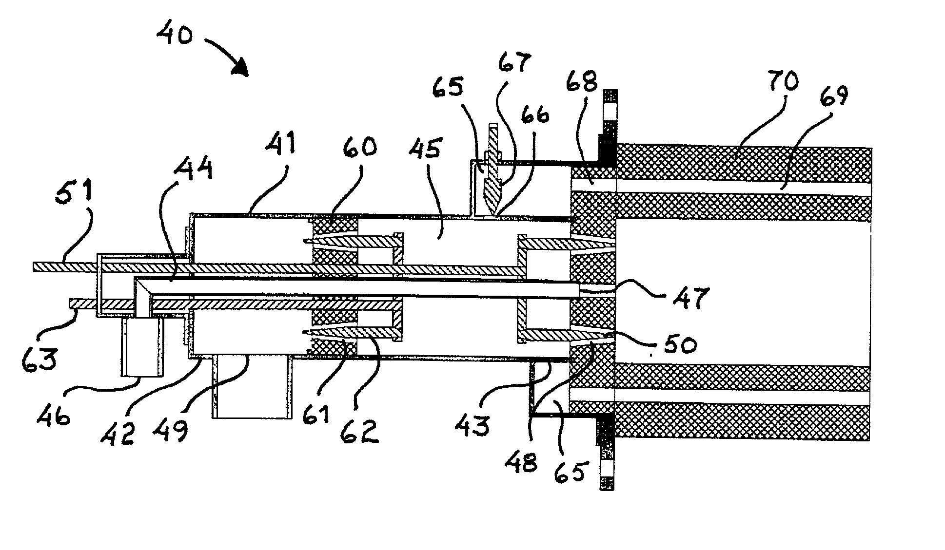
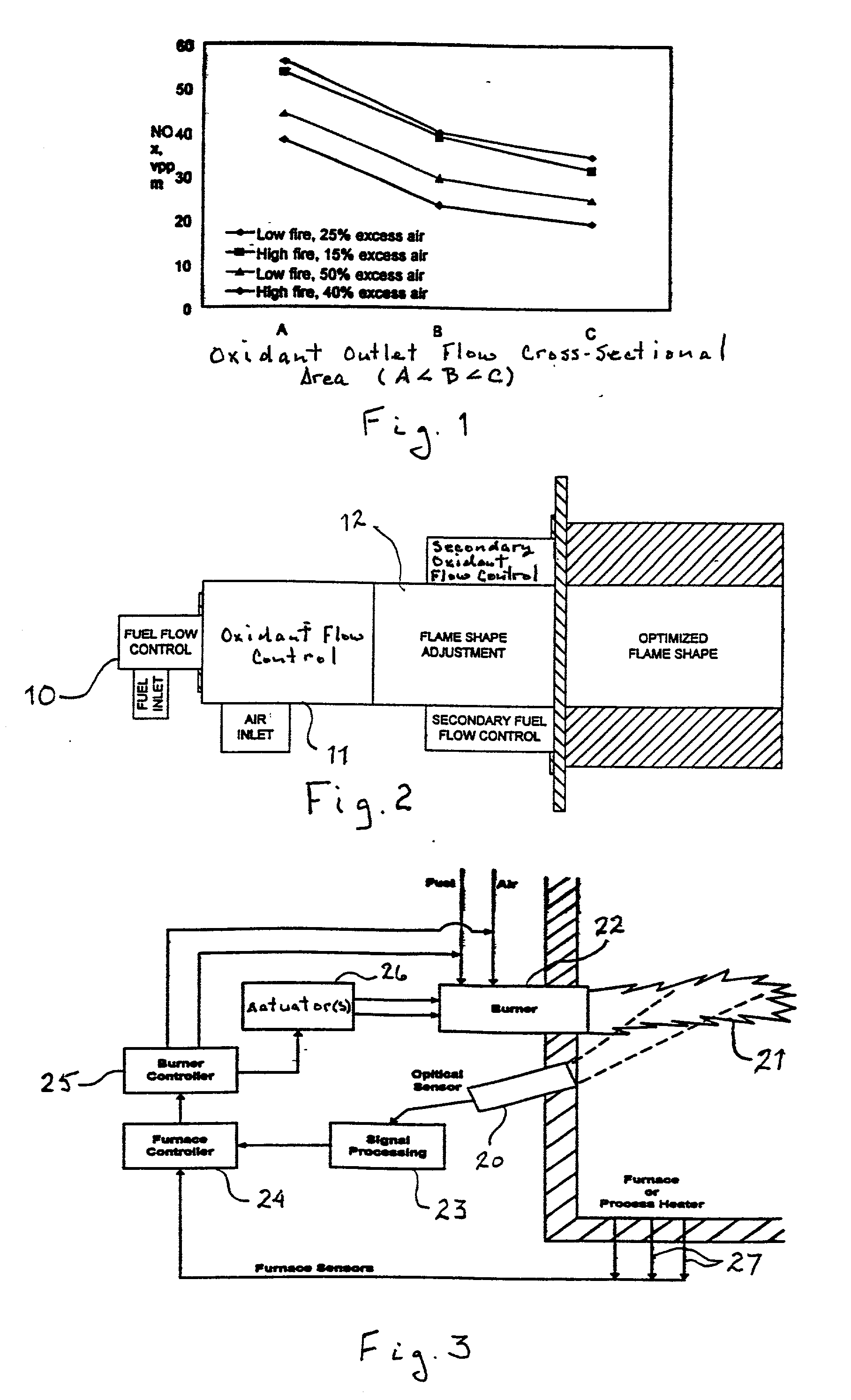
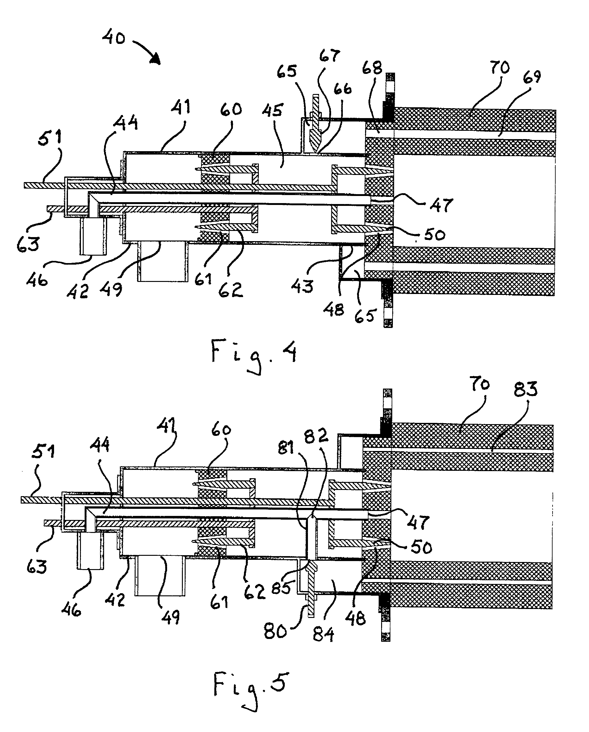
[0017] The invention claimed herein is a self-optimizing combustion system which provides interactive and flexible control of the combustion process in furnaces and other combustion chambers. The flexibility to provide controlled heat transfer to a load over high turndown ratios, with multiple fuels, and during both steady-state and transient operation is provided by combining two components, a flexible-flame burner in accordance with embodiments shown in FIGS. 4, 5 and 6 and a real-time flame sensing and control system as shown in FIG. 3.

[0018] The flexible-flame burner of the combustion system of this invention can be adjusted for firing rate and for oxidant / fuel ratio as well as for flame shape and degree of oxidant / fuel mixing. FIG. 1 shows the results of operation of a flexible-flame burner in accordance with one embodiment of this invention. As shown, operating the flexible flame burner at constant fire and constant excess air produced as much as twice as much NO.sub.x at air ...


PUM


Abstract

A combustion system for automatic, real-time control of a combustion process which can be applied with significant advantage to a wide range of furnaces, boilers and combustors. The system includes a burner body having a primary first fluid inlet end forming at least one primary first fluid inlet and a first fluid outlet end forming at least one first fluid outlet. An inner conduit is disposed within the burner body, forming a fluid flow region between the burner body and the inner conduit. The inner conduit has a second fluid inlet distal from the first fluid outlet and a second fluid outlet proximate the first fluid outlet. An internal adjustment device is provided for adjusting a flow cross-sectional area for a first fluid and / or a second fluid disposed within the burner body.

Description

[0001] 1. Field of the Invention[0002] This invention relates to combustion systems having means for automatic, real-time control of the combustion process which can be applied with significant advantage to a wide range of furnaces, boilers and combustors. This invention also relates to a burner for said combustion system which, in addition to means for adjusting the firing rate and air / fuel ratio, also comprises means for adjusting flame size and shape and the degree of mixing of fuel and oxidant.[0003] 2. Description of Prior Art[0004] For many years, efforts in the area of combustion have been focused on improving burner efficiency and lowering emissions from the combustion process. These efforts have provided significant advances in burner technology while increasing efficiency and lowering emissions. However, these effort have provided diminishing returns to combustion system operators. Currently, the greatest potential for furnace combustion improvement rests with taking a mor...

Claims


Application Information

Patent Timeline
IPC IPC(8): F23C7/00F23D14/22F23D14/60
CPCF23C7/008F23D14/22F23D14/60F23N2025/16F23N2035/06F23N2225/16F23N2235/06
Inventor ABBASI, HAMID A.RUE, DAVID M.WAGNER, JOHN C.
Owner GAS TECH INST
Why Eureka
Try Eureka