
Method to perform downlink power control in packet switching cellular systems with dynamic allocation of the RF channel

a packet switching cellular system and power control technology, applied in the direction of power management, sustainable buildings, wireless communication, etc., can solve the problems of not always assured, outlined problems arise for mobile stations with an uplink tbf, and problems in the performance of downlink power control

Inactive Publication Date: 2003-03-20
SIEMENS INFORMATION & COMM NEWTWORKS INC
View PDF3 Cites 60 Cited by
  • Summary
  • Abstract
  • Description
  • Claims
  • Application Information

AI Technical Summary

Benefits of technology

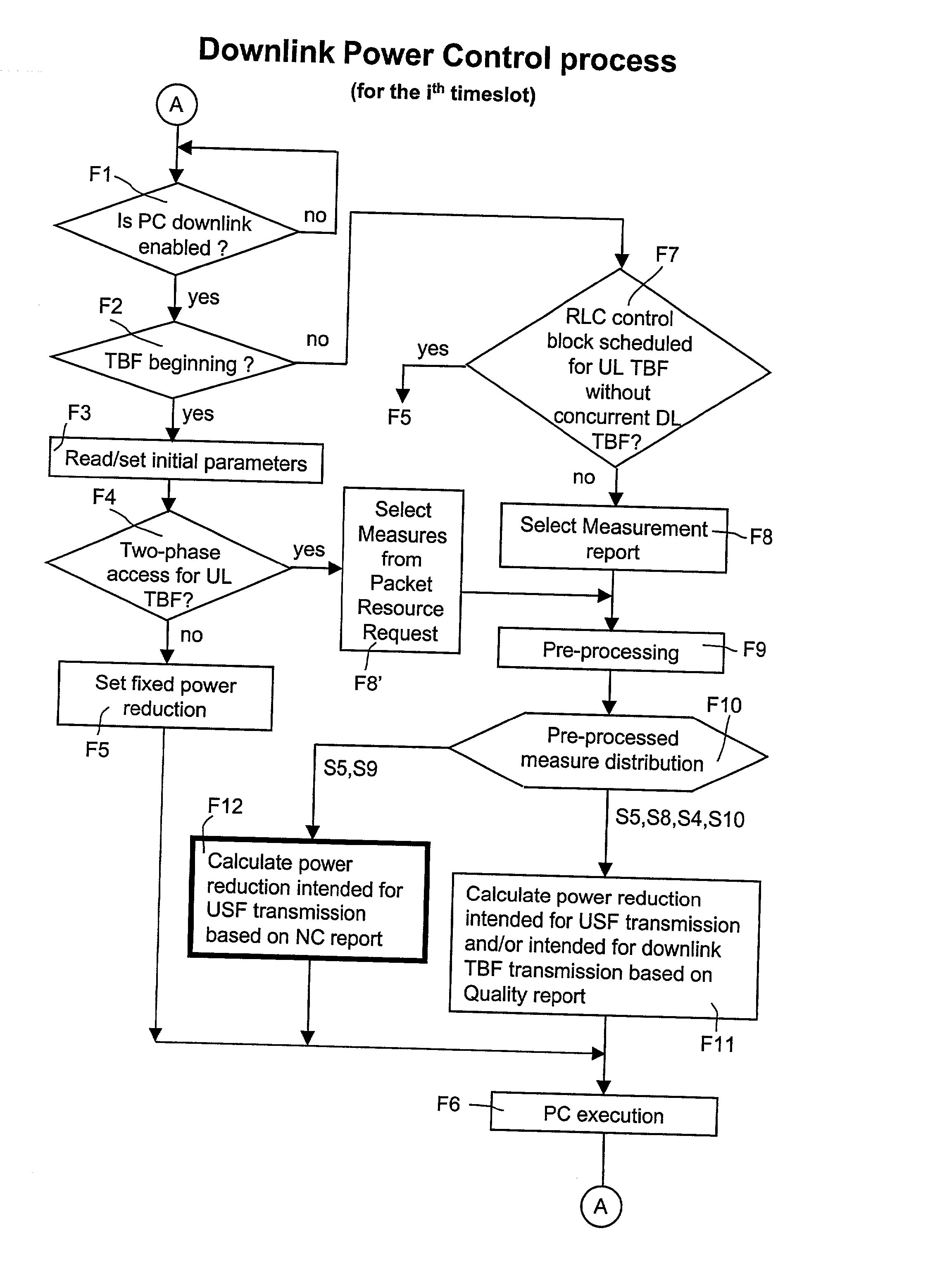
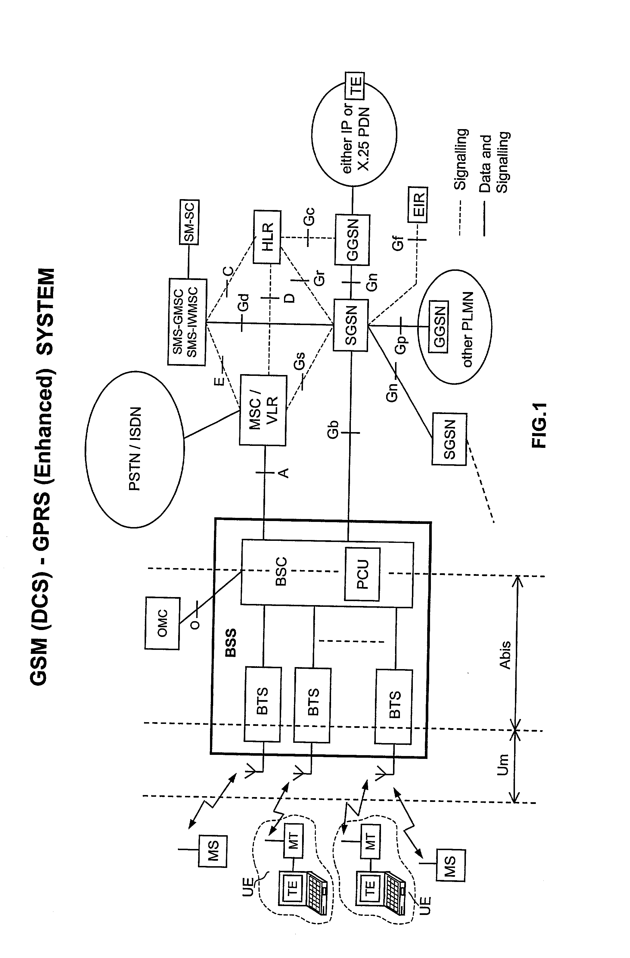
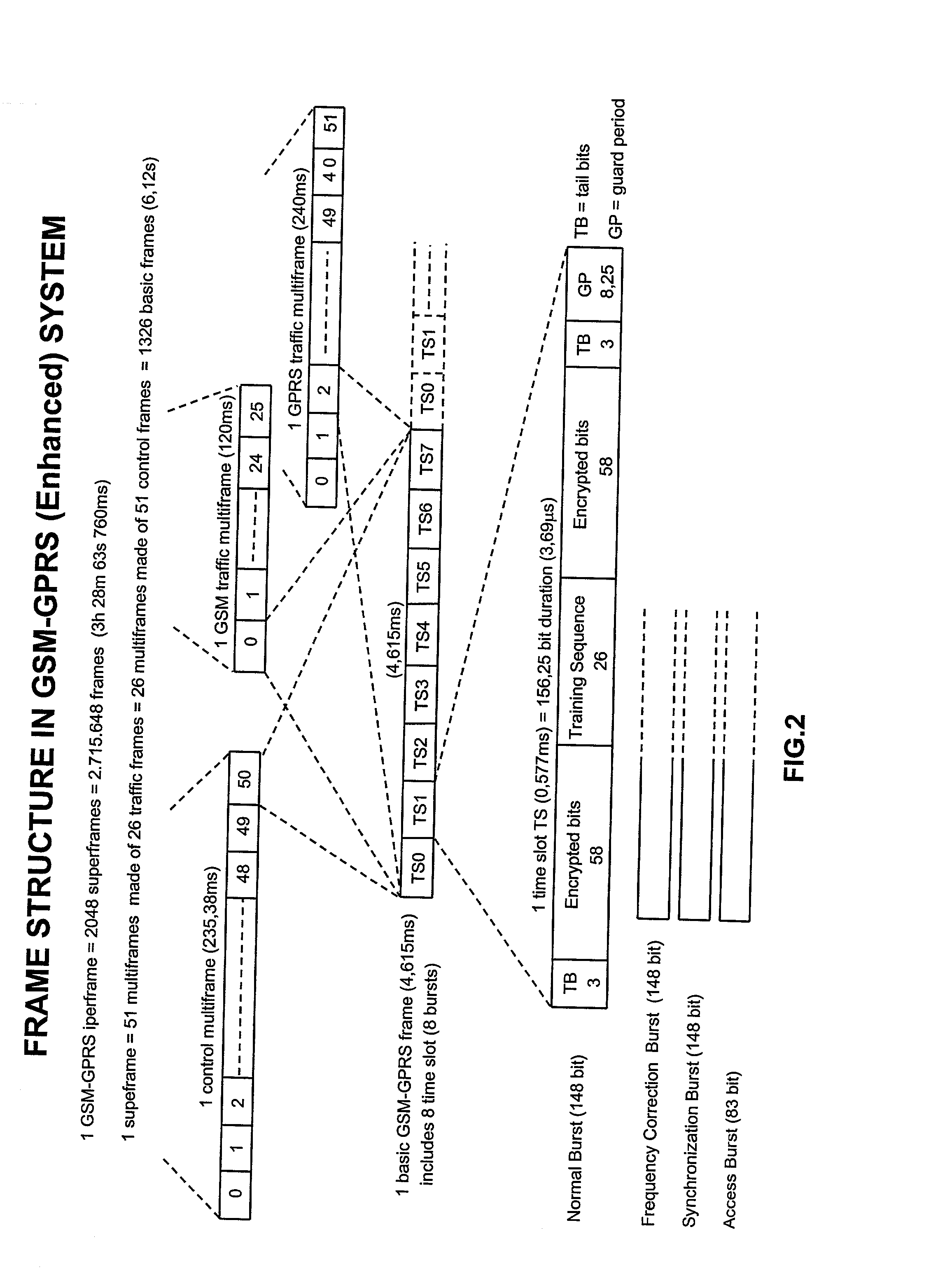
[0036] To achieve said purposes the subject of the present invention is a power control method, as disclosed in the claim 1.[0037] From the wording of the claim it can be appreciated that the power control method of the invention in subject takes effective precautions against the uncertainty on the RF channel conditions, due to the unknown effect of the interference. The feedback countermeasures adopted by the method of the invention dynamically correct the transmissible power, in order to minimize unsuccessful in the USF decoding. A mobile station without downlink TBF is served at best from a BTS operating in conformity with the disclosed method and can reaches greater data-rates on the uplink connection. The risk of the uplink TBF release is minimized consequently.[0038] Further objects and advantages of the present invention will be made clear by the following detailed description of an embodiment thereof and the annexed drawings given for purely non-limiting explanatory purposes and wherein:[0039] FIG. 1 shows an GSM and GPRS radiomobile network operating in conformity with the method of the present invention;[0040] FIG. 2 shows a Time Division Multiple Access (TDMA) multiframe structure common to the GSM and GPRS of FIG. 1;[0041] FIG. 3a shows a GSM traffic channel multiframe;[0042] FIG. 3b shows an GPRS traffic channel multiframe;[0043] FIG. 4 shows the mapping of higher level frames into radio blocks belonging to the EGPRS multiframe of FIG. 3b;[0044] FIG. 5 shows the functional blocks of a base station BTS of FIG. 1 operating in conformity with the method of the present invention;[0045] FIG. 6 shows a GPRS RLC data block with MAC header;[0046] FIG. 7 shows a GPRS RLC control block with MAC header;[0047] FIG. 8 shows a high level flow-chart of the power control method of the present invention;[0048] FIG. 9 shows a flow-chart which details a Measurement Report selection step F8 of the high level flow-chart of the preceding FIG. 8;[0049] FIG. 10 shows a flow-chart which details a power reduction calculation step F12 mostly representative of the present invention and belonging to the high level flow-chart of the preceding FIG. 8;[0050] FIG. 11 shows a curve which links C / I to the maximum achievable throughput per timeslot, usable to set a (C / I).sub.TARGET to be introduced into a power reduction calculation step F1 which belongs to the high level flow-chart of the preceding FIG. 8.

Problems solved by technology

The outlined USF mechanism causes some problems in the performance of downlink Power Control (PC).
The problem arises because the dynamic allocation of the data packets forces at least two mobile stations to both reliable receive the same data packet (RLC / MAC Radio Block) transmitted by the BTS.
The network, to perform this task in the right way, has to known quality and attenuation on both downlink radio channels of the two mobile stations concerned; that implies the existence of at least the two downlink TBFs (the ideal condition being concurrent TBFs for each mobile station), but this is not always assured due to the reciprocal independence of uplink from downlink TBF assignment.
In conclusion, the outlined problem arises for mobile stations with an uplink TBF only.
The reason behind this is that the transmitter power directly affects the quality of the radio link, so that the received signal may be dominated by cochannel interference.
The drawback of the outlined downlink GPRS power control procedure is the complete absence of any countermeasures against the intrinsic unreliability of the calculated power reduction threshold (T_LEV_USF), mainly due to the unknown effect of the interference.
The network is consequently unable to properly correct the entity of the power reduction in order to avoid that the USF flag be too frequently unlistened by an addressed mobile station.
These drawbacks become particularly serious in those environments characterized by strong cochannel interferers such as the small urban cells.

Method used


Image

  • Method to perform downlink power control in packet switching cellular systems with dynamic allocation of the RF channel
  • Method to perform downlink power control in packet switching cellular systems with dynamic allocation of the RF channel
  • Method to perform downlink power control in packet switching cellular systems with dynamic allocation of the RF channel

Examples


Embodiment Construction

[0051] FIGS. 1, 2, 3a, 3b and 4 have already been duly discussed above.

[0052] FIG. 5 shows a block diagram of a Base Transceiver Station (BTS) which takes part in the present invention by performing a more reliable transmission of the USF flag. The BTS station of FIG. 5 includes a TRANSMITTING SECTION and a RECEIVING SECTION both controlled through a BTS CONTROL PROCESSOR & RAM block, which further controls a Frequency Synthesizer & Hopping unit common to the two sections. The two Sections and the BTS CONTROL PROCESSOR & RAM block are connected to an A-Bis INTERFACE functional block for receiving / outputting one or more 2 Mb / s PCM link carrying PCU frames incoming from, or outgoing to, the BSC block (FIG. 1). A BRANCHING UNIT placed between the antenna and the two BTS sections includes a Duplexer filter which conveys to the antenna the global RF output signal of the TRANSMITTING SECTION, and to the input of the RECEIVING SECTION the wide band RF signal received on the antenna. The BR...


PUM


Abstract

The invention discloses a method to perform downlink Power Control in packet switching cellular systems with dynamic allocation of the RF channel, such as GPRS / EGPRS. The performances concern a scenario in which a radio block transmitted from the Base Station (BTS) on a downlink channel has to be received from at least two MSs simultaneously, a first MS being the addressee of the data / control packet on the downlink TBF while the second MS being the addressee of the Uplink State Flag (USF) for scheduling transmission of the next data / control packet from an uplink TBF to an uplink shared channel. First MS transmits to the BTS a first measurement report including measures of BCCH level and interference level on all the timeslots, while the second MS transmits a NC report including measures of BCCH level only, that because detailed interference measure on the downlink channel are prevented due the absence of a concurrent downlink TBF. The measures are averaged in as many running average filters and the averages compared with target thresholds to find a first and a second power reduction intended for USF and packet transmission respectively. A final power reduction is selected from the two for the next PC execution step. Target threshold for the first MS's averaged measures is a C / I value which provides maximum achievable net throughput independently of Coding Scheme. Target threshold for the second MS depends on CS of the USF flag in a way that when the mean value of the level measures is equal to the threshold a fixed probability takes place that the USF flag is decoded with success. The network, in the capacity of the BSC and PCU, counts successfully and unsuccessfully blocks received uplink upon transmission of the scheduled USFs for that uplink TBF, being the lack of a scheduled block noticed by the network. If successfully counting reaches a fixed maximum counting before, then an increment of the first power reduction is decided, while in case the maximum unsuccessfully counting is reached before a decrement of the first power reduction is instead decided (FIG. 10).

Description

[0001] The present invention relates to the field of radiomobile communication systems and more precisely to a method to perform downlink Power Control in packet switching cellular systems with dynamic allocation of the RF channel.[0002] The known GSM-GPRS / EGPRS cellular system appears as the most relevant prior art on the field of the present invention, so before the disclosure of the invention the following panoramic on the system is given, taking advantage from the large GSM specifications coming from ETSI (European Telecommunications Standards Institute). Details on the constitution of the apparatuses and on the power control procedure will be given in the non-limiting embodiment.[0003] The so-called General Packet Radio Service (GPRS) has been added to the Global System for Mobile communications (GSM) in order to achieve higher performance with data handling. This object is met by the introduction of a packet switching feature which doesn't request fixed connections for all the...

Claims


Application Information

Patent Timeline
IPC IPC(8): H04B7/005
CPCH04W52/367H04W72/0473H04W72/1231H04W72/1284Y02B60/50H04W72/542H04W72/21
Inventor MASSERONI, CARLOPAROLARI, SERGIO
Owner SIEMENS INFORMATION & COMM NEWTWORKS INC
Learn More