
Video noise reduction method using adaptive spatial and motion-compensation temporal filters

a technology of temporal filter and adaptive spatial compensation, applied in the field of video noise reduction, can solve the problems of principal sources of noise in digital images, no images are absolutely perfect, and noise in the generated images

Active Publication Date: 2010-06-01
HUPER LAB
View PDF14 Cites 22 Cited by
  • Summary
  • Abstract
  • Description
  • Claims
  • Application Information

AI Technical Summary

Problems solved by technology

But no images are absolutely perfect no matter how good a camera is, since images are interfered with by the presence of noise.
The principal sources of noise in digital images arise during image acquisition (digitization) and / or transmission.
For instance, in acquiring images with a CCD camera, luminosity and sensor temperature are major factors affecting the amount of noise in the generated images.
Images are corrupted during transmission principally due to interference in channels used for transmission.
For example, an image transmitted by a wireless network might be disturbed as a result of lightning or other atmospheric charged particles.
In addition, due to a sensing element with one pixel consisting of a transistor, instability of the transistor will always cause the sensing element a permanent or transient failure.
That is so-called transient noise and permanent noise in image sequences.
Image sequences are often corrupted by noise in different production ways, such as a bad reception of television pictures.
These algorithms are necessary, since the presence of noise in an image sequence degrades both its visual quality, as well as, the effectiveness of subsequent processing tasks.
This entropy of the image sequence is increased obviously by the noise.
This kind of noise arose from the failures of the image sensors.
It is generally caused by flaws in the manufacture of transistors, so the permanent noise always appears at the same locations in images.
The main reason is due to interferences by external environment or due to instability of sensing elements.
Due to the lack of robust motion estimators, early attempts at temporally filtering image sequences were restricted to simple frame average techniques.
However, in a real situation, due to the presence of ambient illumination or TV monitor characteristics, noise in dark areas tends to be less visible than that in regions of high luminance.
Then the results of post-processing tasks are also influenced by noise.
For video-noise filtering, it may cause object-overlapped phenomenon in an image frame due to the occlusion problem when the spatial-filtering is only used, excluding the temporal-filtering.
Oppositely, the image may be blurred and even the noise cannot be filtered if the temporal-filtering is only performed but spatial characteristics of the image are not utilized.
Therefore, there are residual images or fuzzy phenomenon appearing when an object moves due to motion estimation not being used to detecting whether an object is moving or not.
This may blur outline edges of image after filtering noise due to problems of spatial outline edges of image, permanent noise, and temporary transient noise are not considered.
The spatial filtering is added due to noise interference affecting accuracy of motion estimation.
However, the output of the front end cannot reduce noise sufficiently, Boyce's detector are used for motion compensation.
A method provided in the prior art reference document considers both characteristics in the spatial and temporal domains, but is applied to reduce Gaussian noise only but not to reduce impulse noise effectively.

Method used


Image

  • Video noise reduction method using adaptive spatial and motion-compensation temporal filters
  • Video noise reduction method using adaptive spatial and motion-compensation temporal filters
  • Video noise reduction method using adaptive spatial and motion-compensation temporal filters

Examples


Embodiment Construction

[0040]Some concepts of the present invention have already been published in the proceedings of conference, as described below: (Thou-Ho (or Chao-Ho) Chen), Chao-Yu Chen and Tsong-Yi Chen, “An Intelligent Video Noise Reduction Method Using Adaptive Spatial and Motion-Compensation Temporal Filters”, 2006 IEEE International Conference on Cybernetics&Intelligent Systems (CIS), Bangkok, Thailand, Jun. 7-9, 2006. (pp. 341-346).

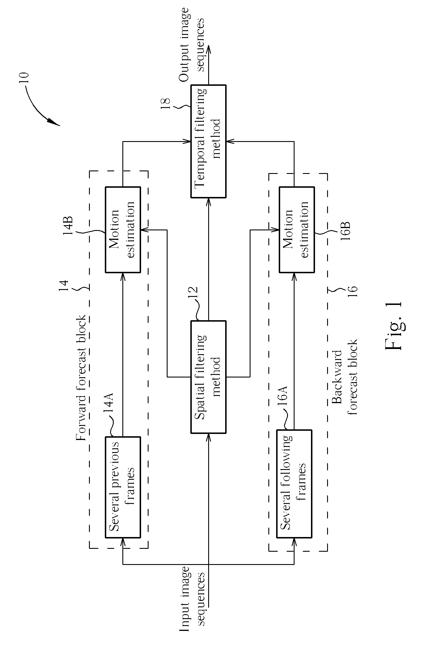
[0041]The present invention provides a video reduction method using adaptive spatial and motion-compensation temporal filters. The present invention can be seen in several levels. The first introduces approximated motion compensated spatiotemporal filtering. The next is an algorithm introducing a temporal filter for reducing noise and related filters. Finally, temporal relationships of a video, correct motion estimation, and compensation of image sequences after spatial filtering are fully employed. The temporal relationships can be improved due to motion compensati...


PUM


Abstract

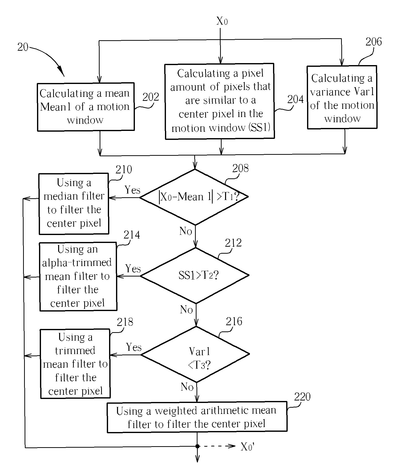
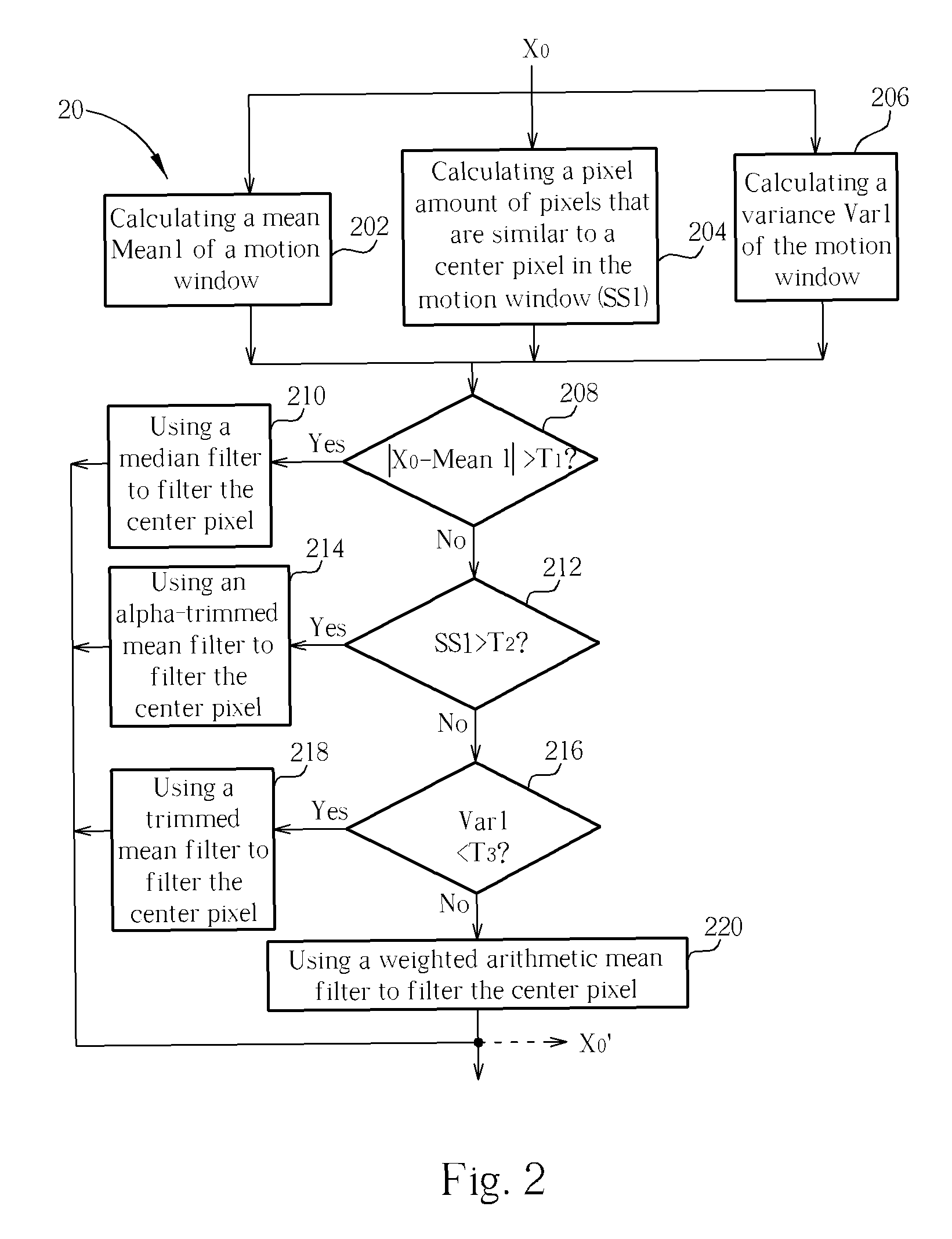
A method includes calculating a mean of a plurality of pixels of a motion window, calculating a pixel amount of pixels similar to a center pixel, calculating a variance of the pixels, determining whether a difference between the center pixel and the mean is greater than a first predetermined value, determining whether the pixel amount similar to the center pixel is greater than a second predetermined value if the difference between the center pixel and the mean is not greater than the first predetermined value, determining whether the variance is smaller than a threshold value if the pixel amount similar to the center pixel is not greater than the second predetermined value, and filtering the center pixel according to a result of determining whether the variance is smaller than the threshold value. Finally, temporal weighted mean filters involving motion estimation are used for motion compensation in images after spatial filtering.

Description

CROSS REFERENCE TO RELATED APPLICATIONS[0001]This application claims the benefit of U.S. Provisional Application No. 60 / 766,976, filed Feb. 22, 2006, and included herein by reference.BACKGROUND OF THE INVENTION[0002]1. Field of the Invention[0003]The present invention relates to a video noise reduction method, and more particularly, to a video noise reduction method using adaptive spatial and motion-compensation temporal filters.[0004]2. Description of the Prior Art[0005]In an era of multimedia communication, image data is playing an important role. But no images are absolutely perfect no matter how good a camera is, since images are interfered with by the presence of noise. The principal sources of noise in digital images arise during image acquisition (digitization) and / or transmission. The performance of imaging sensors is affected by a variety of factors, such as environmental conditions during image acquisition, and by the quality of the sensing elements themselves. For instanc...

Claims


Application Information

Patent Timeline
Patent Type & Authority Patents(United States)
IPC IPC(8): G06K9/40G06K9/38H04N5/00H04N5/217
CPCH04N5/21H04N5/144
Inventor CHEN, CHAO-HOWU, MING-KUN
Owner HUPER LAB
Learn More