Method of down-chain power control in packet switching cellular system

A downlink and power control technology, applied in the field of downlink power control, can solve problems such as strong cooperative channel interference, unreliable uplink connection, inability to comply with transmission delay or other quality objectives, and achieve high data rate, prevention of uncertainty, and risk reduction effects

Inactive Publication Date: 2003-02-05
SIEMENS INFORMATION & COMM NEWTWORKS INC
View PDF0 Cites 25 Cited by
  • Summary
  • Abstract
  • Description
  • Claims
  • Application Information

AI Technical Summary

Problems solved by technology

Too many reallocations means that the uplink connection is unreliable and cannot comply with transmission delay or other quality goals, so the connection should be released as soon as possible
These disadvantages become particularly severe in environments characterized by strong co-channel interference, such as small suburban cells

Method used


Image

  • Method of down-chain power control in packet switching cellular system
  • Method of down-chain power control in packet switching cellular system
  • Method of down-chain power control in packet switching cellular system

Examples


Embodiment Construction

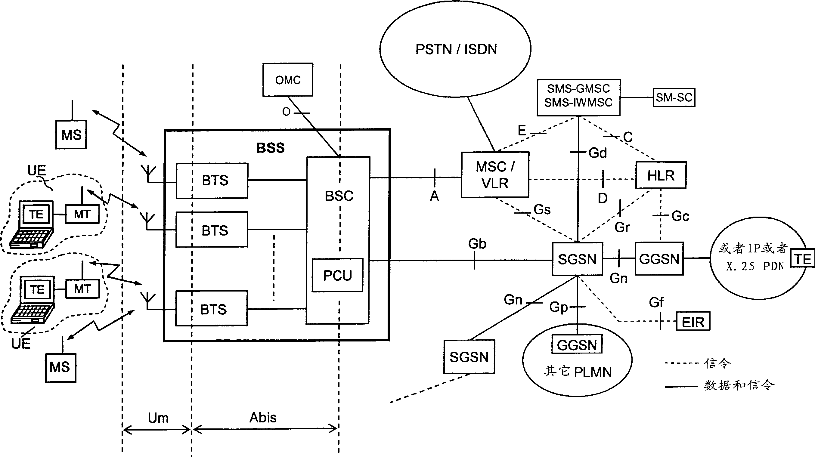
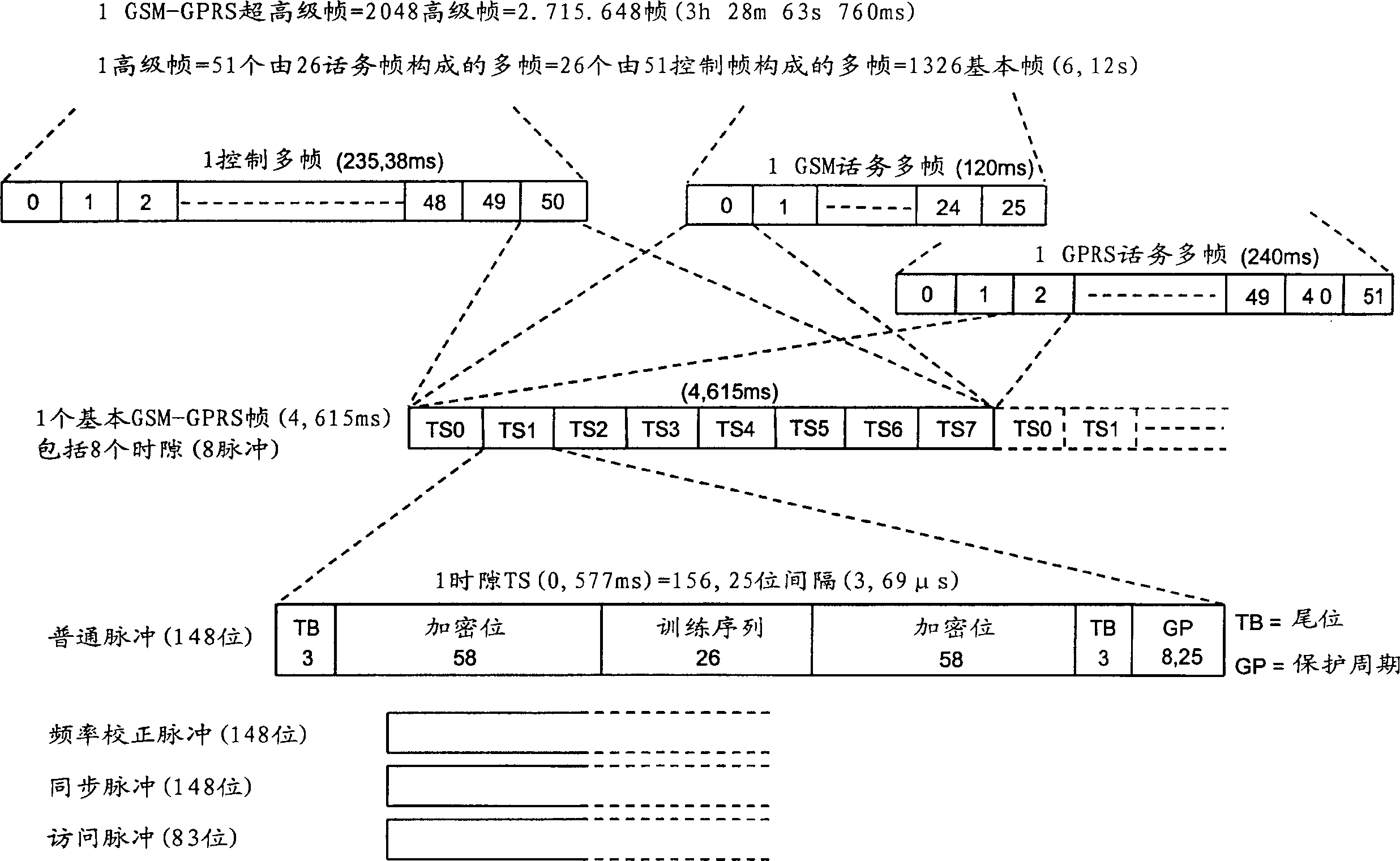
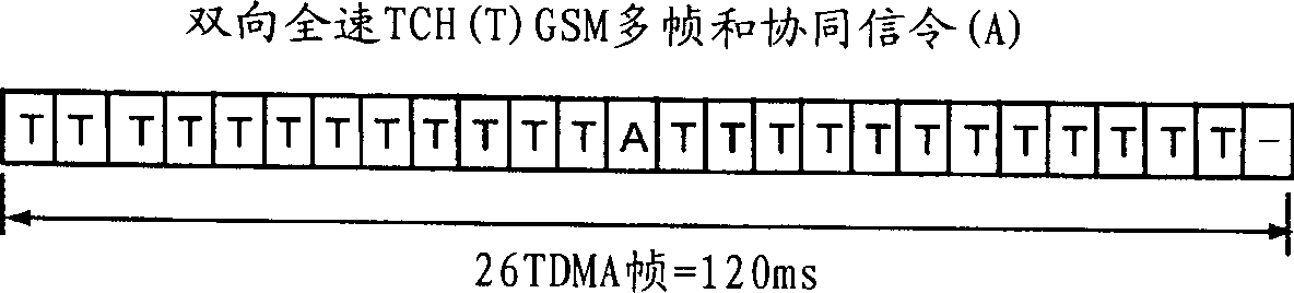
[0028] Figures 1, 2, 3a, 3b and 4 have been discussed above as appropriate.

[0029]Figure 5 is a block diagram illustrating a base transceiver station (BTS) incorporated into the present invention by implementing more reliable transmission of USF flags. The BTS station of Fig. 5 comprises both through BTS control processor and RAM (BTS CONTROL PROCESSOR & RAM) block control transmitting section (TRANSMITTING SECTION) and receiving section (RECEIVING SECTION), and this BTS control processor and RAM block also control the two Part of the shared frequency synthesizer and forwarding (FrequencySynthesizer&Hopping) unit. These two parts and the BTS control processor and RAM block are connected to the A-Bis interface functional block for receiving / outputting one or more 2Mb carrying PCU frames from or to the BSC block (Fig. 1) / s PCM stream (link). The branching unit (BRANCHING UNIT) between the antenna and the two BTS parts includes a duplex filter that transmits the global RF ou...


PUM


Abstract

The invention discloses a method to perform downlink Power Control in packet switching cellular systems with dynamic allocation of the RF channel, such as GPRS / EGPRS. The performances concern a scenario in which a radio block transmitted from the Base Station (BTS) on a downlink channel has to be received from at least two MSs simultaneously, a first MS being the addressee of the data / control packet on the downlink TBF while the second MS being the addressee of the Uplink State Flag (USF) for scheduling transmission of the next data / control packet from an uplink TBF to an uplink shared channel. First MS transmits to the BTS a first measurement report including measures of BCCH level and interference level on all the timeslots, while the second MS transmits a NC report including measures of BCCH level only, that because detailed interference measure on the downlink channel are prevented due the absence of a concurrent downlink TBF. The measures are averaged in as many running average filters and the averages compared with target thresholds to find a first and a second power reduction intended for USF and packet transmission respectively. A final power reduction is selected from the two for the next PC execution step. Target threshold for the first MS's averaged measures is a C / I value which provides maximum achievable net throughput independently of Coding Scheme. Target threshold for the second MS depends on CS of the USF flag in a way that when the mean value of the level measures is equal to the threshold a fixed probability takes place that the USF flag is decoded with success. The network, in the capacity of the BSC and PCU, counts successfully and unsuccessfully blocks received uplink upon transmission of the scheduled USFs for that uplink TBF, being the lack of a scheduled block noticed by the network. If successfully counting reaches a fixed maximum counting before, then an increment of the first power reduction is decided, while in case the maximum unsuccessfully counting is reached before a decrement of the first power reduction is instead decided (fig.10).

Description

technical field [0001] The invention relates to the field of wireless mobile communication systems, more precisely, relates to a method for performing downlink power control in a packet-switching cellular system by dynamically assigning radio frequency channels. Background technique [0002] The known GSM-GPRS / EGPRS cellular system is the most relevant prior art in the field of the invention, so before disclosing the invention, the following overview of the system is given using the wide GSM specification derived from the European Telecommunications Standards Institute (ETSI) . The details of the configuration of the device and the power control process will be given in the non-limiting examples. [0003] To achieve higher performance in data processing, the so-called General Packet Radio Service (GPRS) was added to the Global System for Mobile Communications (GSM). This object is achieved by introducing a packet switching function that does not...

Claims


Application Information

Patent Timeline
Patent Type & Authority Applications(China)
IPC IPC(8): H04B7/005
CPCH04W72/0473H04W52/367H04W72/1231Y02B60/50H04W72/1284H04W72/542H04W72/21
Inventor 卡洛·马塞罗尼瑟吉奥·帕罗拉里
Owner SIEMENS INFORMATION & COMM NEWTWORKS INC
Why Eureka
Try Eureka