Optical fiber cable assembly with interstitial support members

Inactive Publication Date: 2003-03-27
AFL COMM LLC
View PDF0 Cites 17 Cited by
  • Summary
  • Abstract
  • Description
  • Claims
  • Application Information

AI Technical Summary

Benefits of technology

[0013] The lower modulus of elasticity of the outer interstitial members make them less rigid than the central interstitial member and enables them to be spiral wound around the central interstitial member, together with the buffer tubes. The central interstitial member having a higher modulus of elasticity is not easily spiral wound. In an exemplary embodiment, the outer interstitial members and buffer tubes are wound spirally at a winding pitch between 8 and 20 times a diameter of the optical core, For aerial applications, the outer interstitial members and buffer tubes are preferably wound spirally at a winding pitch between 8 and 16 times the diameter of the optical core. For duct or premise applications, the outer interstitial members and buffer tubes are preferably wound spirally at a winding pitch between 10 and 20 times the diameter of the optical core.

Problems solved by technology

Problems with the prior art design of optical fiber cable assemblies include the inability to reduce the diameter of the optical core or reduce the number of Aramid yarns forming the strength layer surrounding the optical core while maintaining an acceptable degree of mechanical loading capacity of the cable assembly.
Because of these inabilities, no reductions are available in the overall diameter of the optical fiber cable assembly, the circumferences and, hence, weights of the inner and outerjackets, the overall linear weight of the cable assembly or the overall cost of the cable assembly.

Method used


Image

  • Optical fiber cable assembly with interstitial support members
  • Optical fiber cable assembly with interstitial support members
  • Optical fiber cable assembly with interstitial support members

Examples


first embodiment

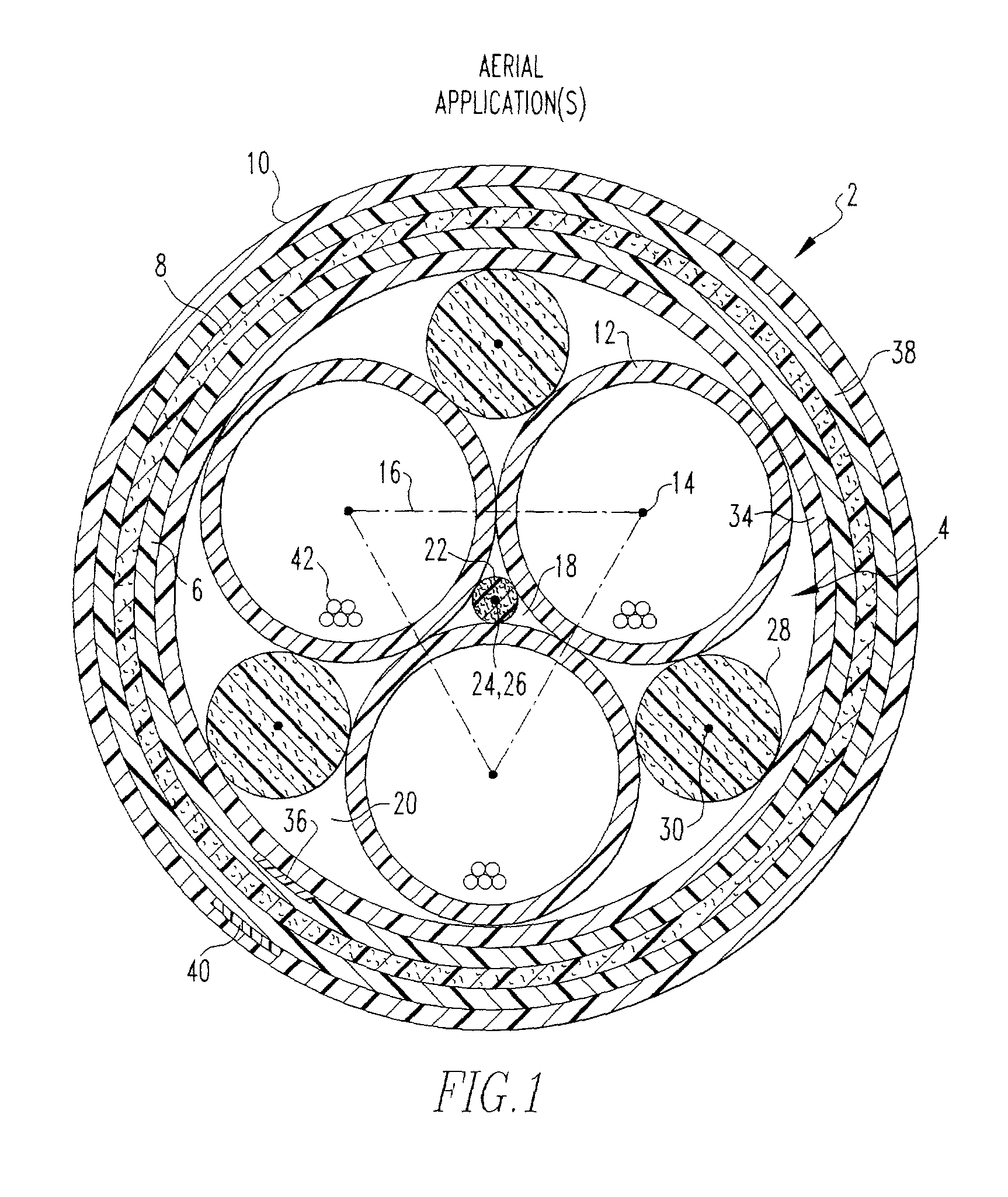
[0022] With reference to FIG. 1, a first embodiment optical fiber cable assembly 2 designed for aerial applications includes an optical core 4 surrounded by an inner jacket 6, a strenght layer 8 and an outer jacket 10. Optical core 4 includes three hollow, elongated and cylindrical buffer tubes 12 arranged with their axes 14 extending in the same direction. When viewed from an end of optical core 4, the axis of each buffer tube 12 is positioned at a comer of an imaginary triangle 16 with the outside diameter of each buffer tube 12 tangent to the two other buffer tubes 12.

[0023] Buffer tubes 12 define therebetween a first, central interstitial space 18 and a plurality of second, outer interstitial spaces 20. More specifically, each pair of adjacent buffer tubes 12 define therebetween on a side thereof opposite first, central interstitial space 18 one of the second, outer interstitial spaces 20.

[0024] A central, elongated outer interstitial member 22 is received in first, central inte...

second embodiment

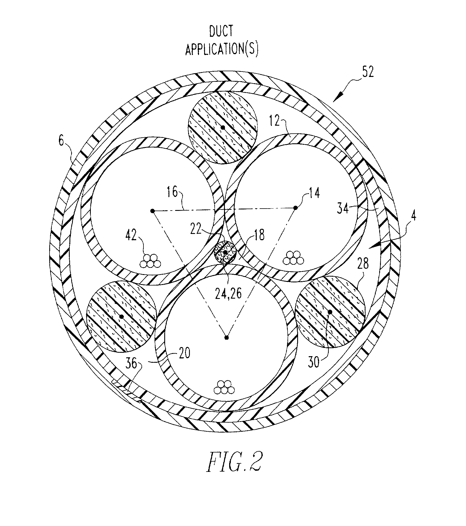
[0036] With reference to FIG. 2 and with continuing reference to FIG. 1, a second embodiment optical fiber cable assembly 52 designed for application in ducts, premises, conduits, raceways, and the like (hereinafter "duct applications"), has the same configuration of optical core 4 as optical fiber cable assembly 2. However, since optical fiber cable assembly 52 is designed for duct applications, outer jacket 10, layer 38 and strength layer 8 in optical fiber cable assembly 2 can be omitted in optical fiber cable assembly 52 whereupon inner jacket 6 becomes the outer jacket. Other than these omissions, optical fiber cable assembly 52 can be the same as optical fiber cable assembly 2.

third embodiment

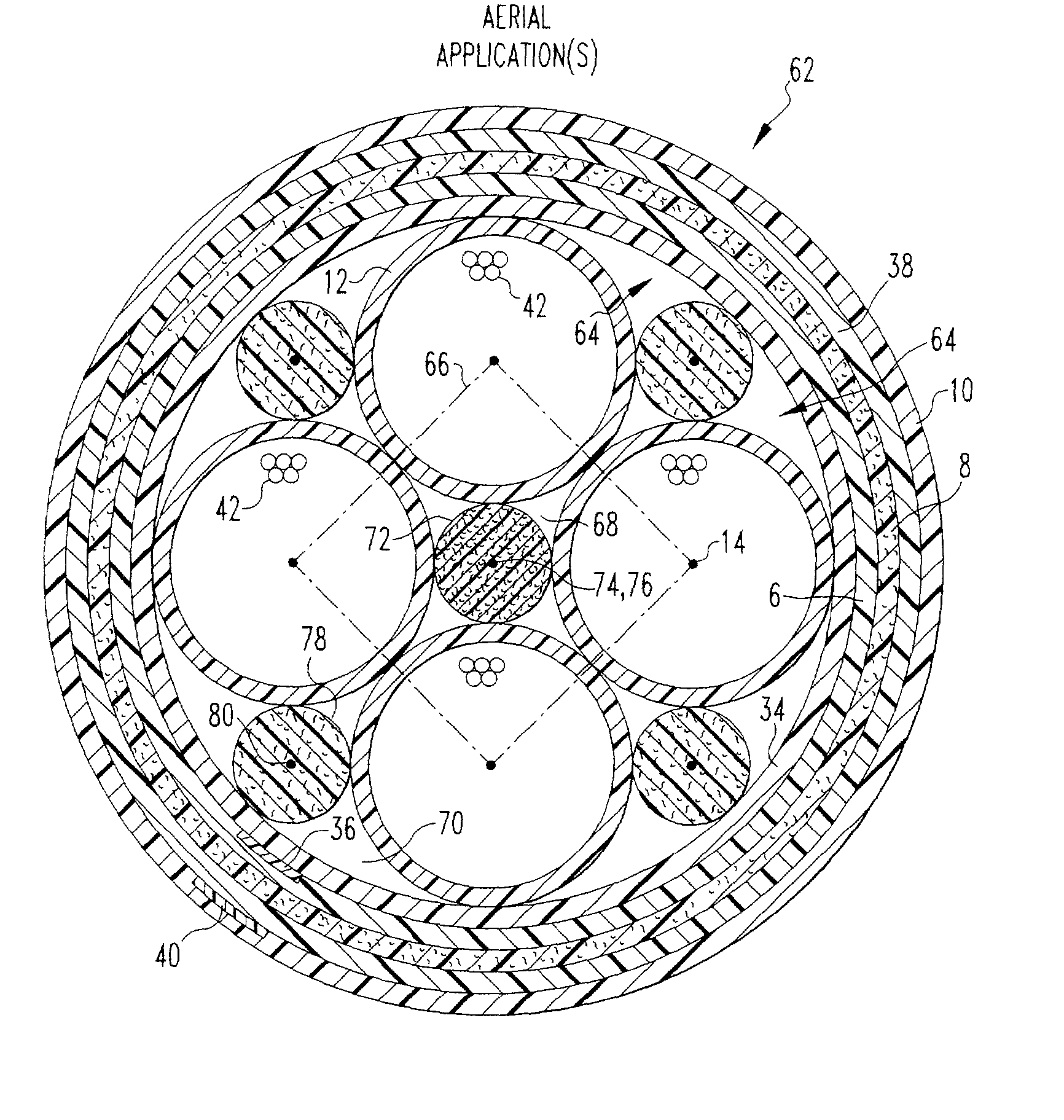
[0037] With reference to FIG. 3, and with continuing reference to FIG. 1, a third embodiment optical fiber cable assembly 62 has an optical core 64 that is surrounded by inner jacket 6, strength layer 8, outer jacket 10 and layers 34 and 38 of Mylar tape and / or polyester binder in the manner described above in connection with optical fiber cable assembly 2. Optical core 64, however, has four buffer tubes 12 arranged with their axes extending in the same direction. When viewed from an end of optical core 64, the axis 14 of each buffer tube 12 is positioned at a corner of an imaginary square 66, with the outside diameter of each buffer tube 12 tangent to two other buffer tubes 12.

[0038] In optical core 64, buffer tubes 12 define therebetween a first, central interstitial space 68 and a plurality of second, outer interstitial spaces 70. More specifically, in optical core 64, each pair of adjacent buffer tubes 12 define therebetween on a side thereof opposite first, central interstitial...


PUM


Abstract

Fiber optic conduits are received around a central axis with their axes extending in the same direction as the central axis and with each fiber optic conduit tangent to two other fiber optic conduits. The fiber optic conduits defme a central interstitial space therebetween and a plurality of outer interstitial spaces between each pair of fiber optic conduits on a side thereof opposite the central interstitial space. A central interstitial member is received in the central interstitial space tangent to the fiber optic conduits and an outer interstitial member is received in each outer interstitial space tangent to the pair of fiber optic conduits defining the outer interstitial space. The central interstitial member has a larger modulus of elasticity than each outer interstitial member.

Description

[0001] This application is a continuation-in-part of U.S. patent application Ser. No. 10 / 093,212, filed Mar. 7, 2002, which is a continuation-in-part of U.S. patent application Ser. No. 10 / 052,807, filed Jan. 23, 2002, which claims the benefit of U.S. Provisional Patent Application Serial No. 60 / 264,549, filed Jan. 26, 2001.[0002] 1. Field of the Invention[0003] The present invention relates to optical fiber cables and, more particularly, to an improved geometrical arrangement and selection of elements foring an optical fiber cable that decreases the diameter, linear weight and cost of the optical fiber cable while, at the same time, improving its mechanical performance.[0004] 2. Description of Related Art[0005] One type of prior art optical fiber cable assembly includes an optical core surrounded by one or more jackets. The optical core includes a plurality, e.g., six, buffer tubes surrounding a central member. Each buffer tube has a wall that encloses a plurality of optical fibers...

Claims


Application Information

Patent Timeline
IPC IPC(8): G02B6/44
CPCG02B6/441G02B6/4422
Inventor MILITARU, CRISTIAN I.
Owner AFL COMM LLC
Why Eureka
Try Eureka