
Cylinder head gasket with seal coatings

Inactive Publication Date: 2003-04-24
ISHIKAWA GASKET CO LTD
View PDF9 Cites 22 Cited by
  • Summary
  • Abstract
  • Description
  • Claims
  • Application Information

AI Technical Summary

Benefits of technology

[0020] According to the structure described above, since the seal coatings are provided on the surfaces of the gasket where an engine component contacts, a sufficient sealing effect is achieved with respect to a scratch, such as a V-notch, larger than a tool mark formed on the sealing surface where the gasket contacts.
[0021] Further, the positions where the sealing lines of the sealing coatings are provided are shifted between a front side and a backside. Thus, the number of the sealing lines is increased, thereby improving the sealing effect.
[0022] Further, the micro seal coatings are provided on the surfaces where the seal coatings are applied, and both sides of the seal coatings are sandwiched and fixed. Thus, the seal coatings are prevented from flowing.
[0023] Also, the seal coating is provided on an area where there is no uneven surface of the bead, thereby causing no negative effect on a function of the bead. Further, the sealing line is provided separate from a sealing line provided by the bead, thereby improving the sealing effect.

Problems solved by technology

As the simple type structure is made of a single plate, only limited types of materials can be used.
However, in the single plate gasket, a kind and a number of sealing members are limited, so that a simplified sealing device has to be used.
Moreover, an area available for the sealing device is limited due to reduction in an engine size.
However, the micro sealing coating can not effectively seal a slightly larger uneven surface like a V-notch and a step with a 20 .mu.m-50 .mu.m depth.
Especially, in a case that a relatively large scratch formed on the surface of the engine member crosses a sealing line formed of the bead or the like, a part of the scratch is not sufficiently sealed.
Thus, the combustion gas, cooling water or oil may leak.
The leaking problem by the scratch such as a V-notch on the sealing surface of the engine member has been a serious problem.

Method used


Image

  • Cylinder head gasket with seal coatings
  • Cylinder head gasket with seal coatings
  • Cylinder head gasket with seal coatings

Examples


first embodiment

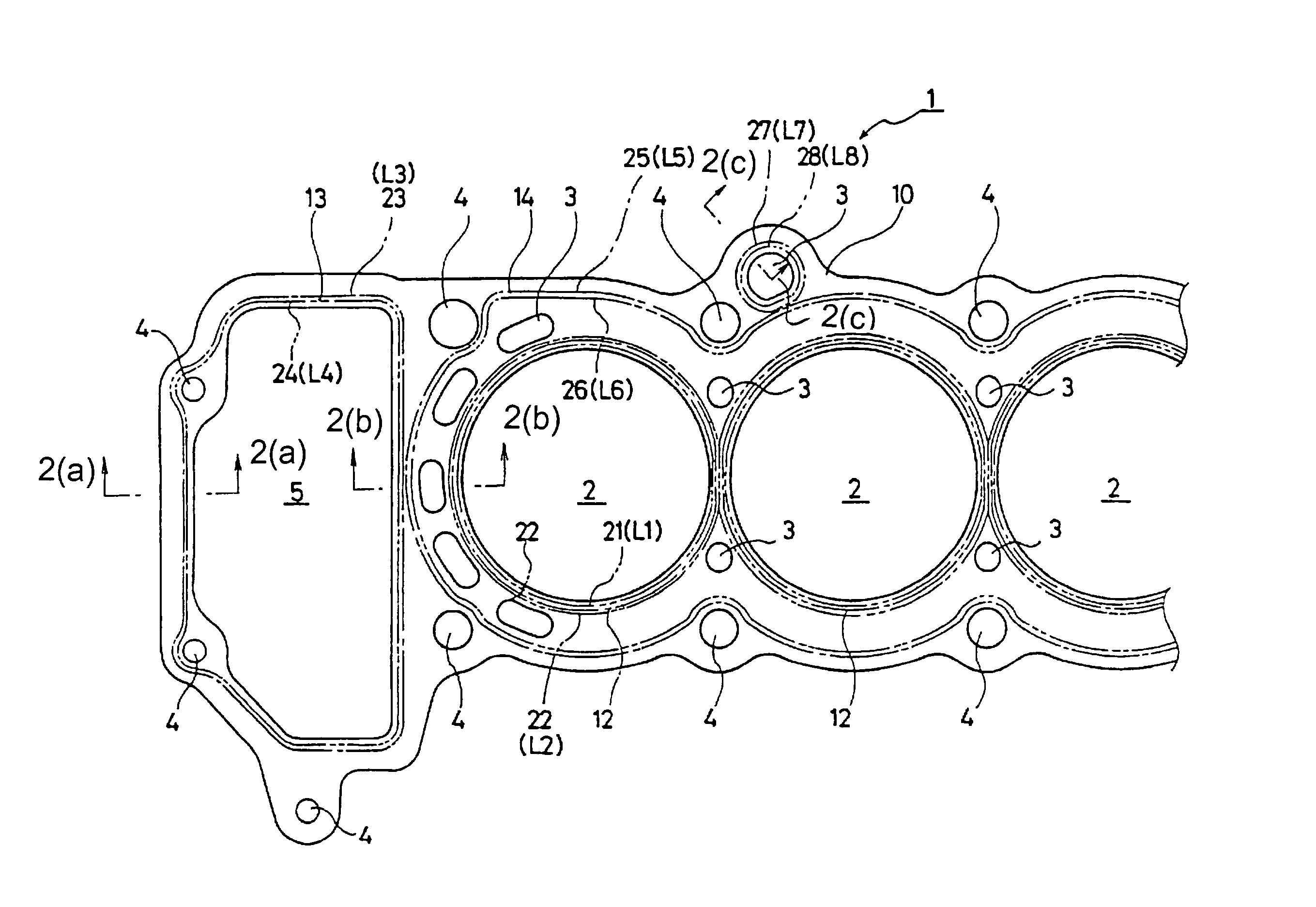
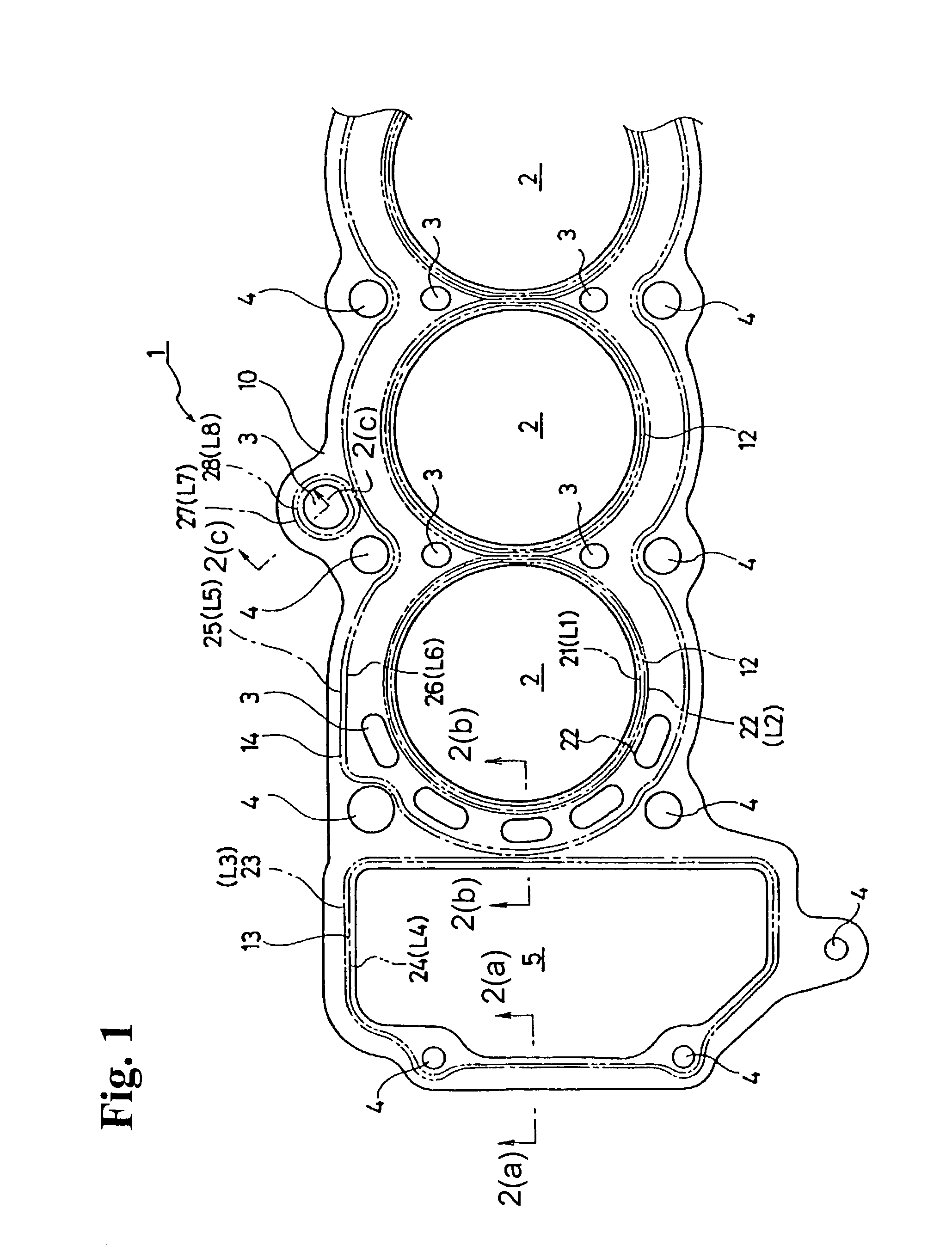
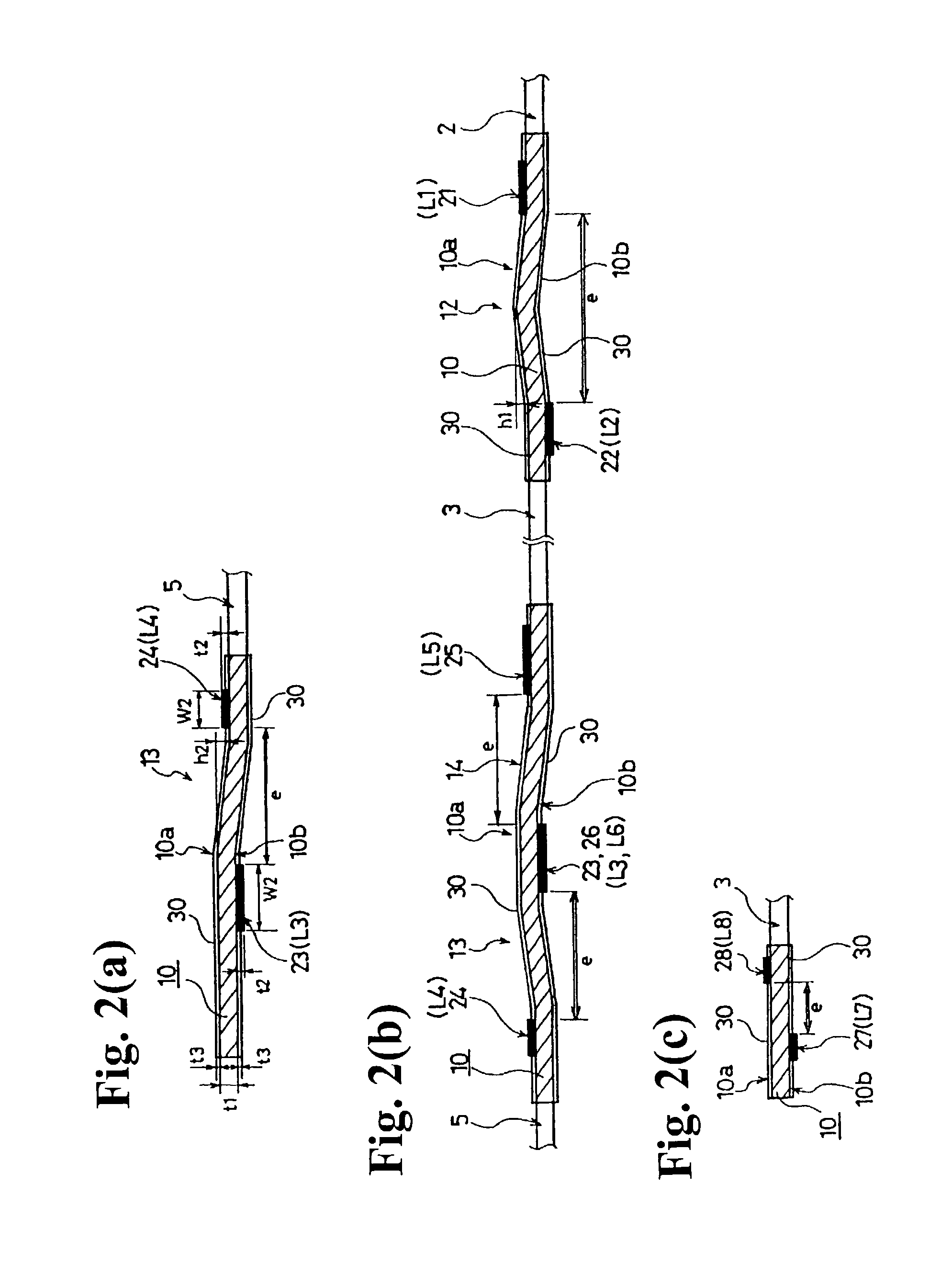
[0031] As shown in FIGS. 1 and 2(a)-2(c), the cylinder head gasket 1 of the first embodiment according to the present invention is formed of a single metal base plate 10 made of annealed stainless steel, heat-treated stainless steel (spring steel), soft steel or the like. The metal base plate 10 is formed to fit a shape of an engine member, such as a cylinder block. A plurality of cylinder bores 2, fluid holes 3, bolt holes 4 for tightening bolts, a gear box hole 5 and the like are formed in the metal base plate 10.

[0032] In the metal base plate 10, there are provided sealing means made of a full bead 12 around the cylinder bores 2, sealing means made of a half bead 13 around the gear box hole 5, and sealing means made of a half bead 14 around a part of the fluid holes 3 such as a cooling water hole and an oil hole.

[0033] In the present invention, as shown in FIGS. 1 and 2(a)-2(b), seal coatings 21-26 made of a foamed coating are formed near the sealing means such as the beads 12, 1...

second embodiment

[0043] Next, a metal gasket 1A (1A') of the second embodiment as shown in FIGS. 3(a) and 3(b) will be explained. The metal gaskets 11A and 1A' as shown in FIGS. 3(a) and 3(b) are formed of two metal plates 11, 12 and a middle plate 13. Seal coatings 21A and 22A (23A, 24A for the metal gasket 1A') are provided on a surface 11a (one surface) of the metal plate 11 and a surface 12a (the other surface) of the metal plate 12, thereby forming sealing lines LA1 and LA2 (LA3 and LA4 for the gasket 1A').

[0044] The sealing line LA1 (LA3) of the sealing coating 21A (23A) formed on the one surface 11a of the gasket 1A (1A') is arranged to shift from a position where the sealing line LA2 (LA4) of the sealing coating 22A (24A) is formed on the other surface 12b.

[0045] Further, the micro seal coatings 30A are made of fluoro rubber or NBR rubber, and are coated on both entire surfaces 11a and 12b of the gasket 1A (1A') by a screen printing to form thin coatings having a hardness H to 2B in pencil h...


PUM


Abstract

A metal gasket seals two engine members of an internal combustion engine. The metal gasket includes a metal gasket member extending substantially throughout an entire area of the engine members and has two surfaces to contact the engine members. At least two seal coatings are coated on the two surfaces of the gasket member to constitute sealing lines on the surfaces of the gasket member. One of the sealing lines on one surface of the metal plate is shifted from the other of the sealing lines on the other surface of the metal plate. Micro coatings are coated on the two surfaces of the gasket member. The thickness of the micro coating is less than that of the seal coating.

Description

BACKGROUND OF THE INVENTION AND RELATED ART STATEMENT[0001] The invention relates to a cylinder head gasket installed between two engine members such as a cylinder head and a cylinder block of an internal combustion engine to seal therebetween.[0002] When joint surfaces between the cylinder head and the cylinder block (a cylinder body) of the engine in an automobile are sealed, a cylinder head gasket is installed therebetween to seal combustion gas, cooling water and the like.[0003] Due to demands for lighter weight and lower cost of the automobile engines, a structure of the cylinder head gasket has been shifted to a simple type formed of a single metal base plate from a laminated type having a number of metal plates. As the simple type structure is made of a single plate, only limited types of materials can be used.[0004] In the laminated type metal plate gasket, a sealing member such as a bead, grommet and shim can be combined as necessity and provided in double for effective sea...

Claims


Application Information

Patent Timeline
IPC IPC(8): F16J15/08F02F11/00
CPCF16J2015/0856F16J15/0818F02F11/00F16J15/08
Inventor NAKAMURA, HIRONOBU
Owner ISHIKAWA GASKET CO LTD
Learn More