Reverse contrast marked package

a reverse contrast and packaging technology, applied in the direction of solid-state devices, basic electric elements, semiconductor devices, etc., can solve the problems of low contrast, difficult to see, and laborious, and achieve high contrast and high visible

Inactive Publication Date: 2003-05-01
AMKOR TECH INC DW US
View PDF0 Cites 19 Cited by
  • Summary
  • Abstract
  • Description
  • Claims
  • Application Information

AI Technical Summary

Benefits of technology

0017] A laser of a laser marking apparatus is fired at the contrast layer to form the mark in the contrast layer. The laser penetrates through the contrast layer and into the upper surface of the encapsulant such that the encapsulant is visible through the mark. Since the encapsulant, e.g., black, has a high contrast relative to the contrast layer, e.g., white, the mark is highly visible and is extremely effective as an advertisement or part identification marking.

Problems solved by technology

Disadvantageously, metal stencil fabrication involved metal etching, which was relatively complex, labor-intensive, time-consuming, and thus expensive.
Thus, laser mark 24 lacked contrast and was difficult to see.

Method used


Image

  • Reverse contrast marked package
  • Reverse contrast marked package
  • Reverse contrast marked package

Examples


Embodiment Construction

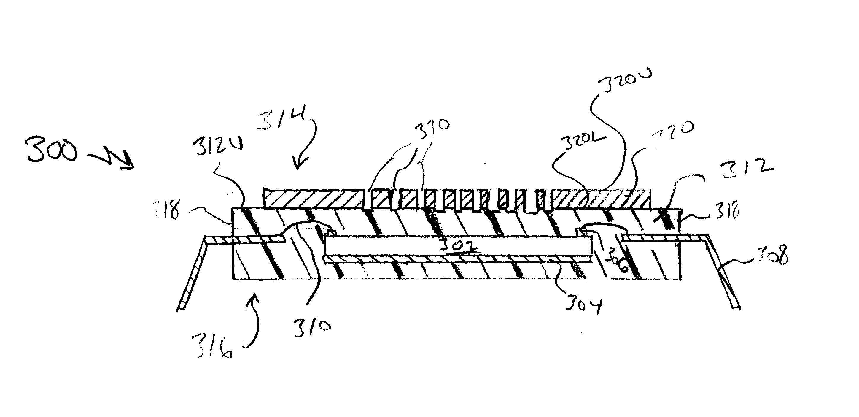
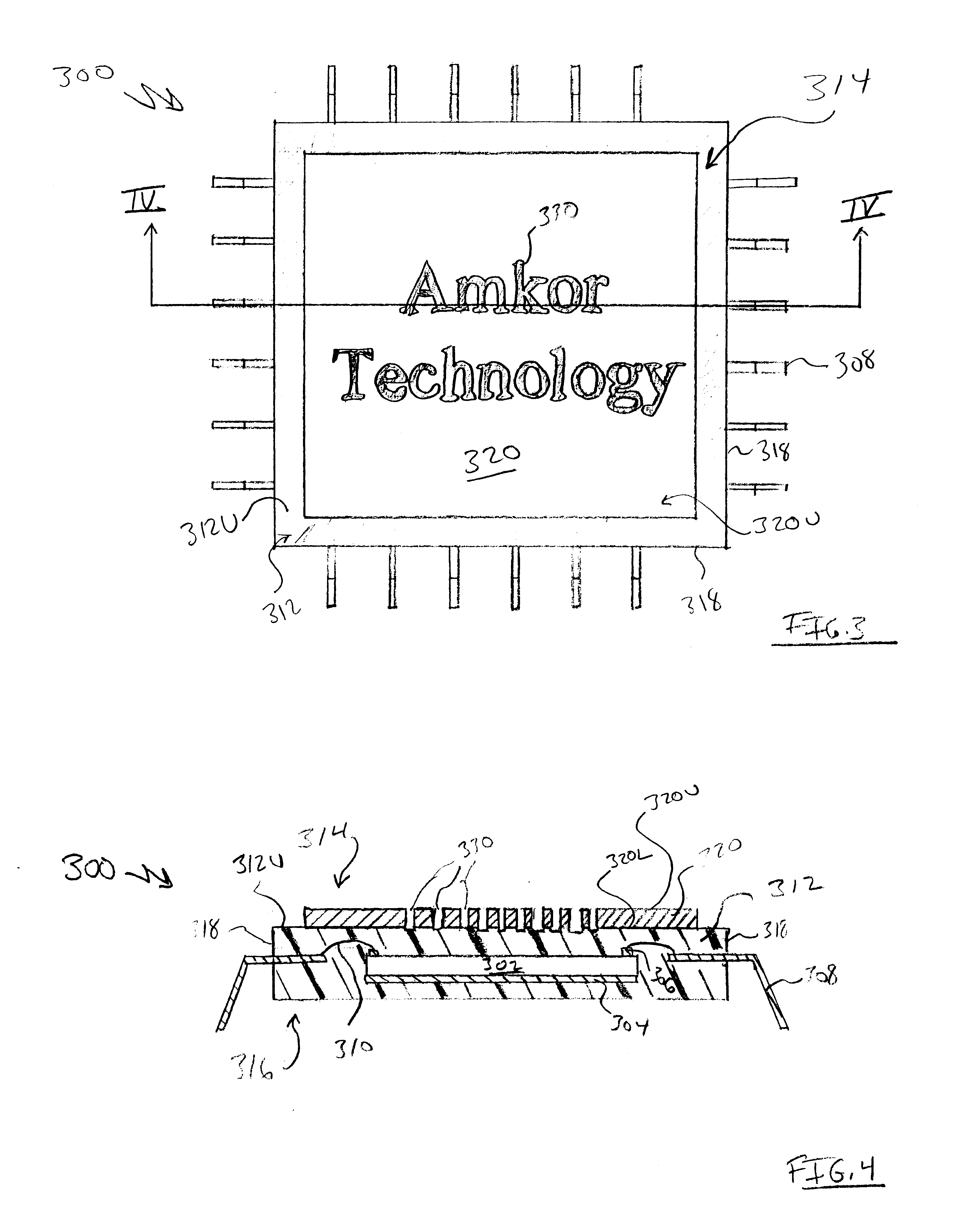
[0027] In accordance with the present invention, a package 300 (FIGS. 3 and 4) includes an electronic component 302 enclosed in an encapsulant 312. Encapsulant 312 has an upper surface 312U and a contrast layer 320 is on upper surface 312U. A mark 330 is in contrast layer 320 and extends through contrast layer 320 such that encapsulant 312 is visible through mark 330.

[0028] Generally, contrast layer 320 has a contrast relative to encapsulant 312. In one particular embodiment, contrast layer 320 is white and encapsulant 312 is black. Since encapsulant 312 is visible through mark 330, mark 330 is the color of encapsulant 312, i.e., black. Since encapsulant 312 has a high contrast relative to contrast layer 320, mark 330 also has a high contrast to contrast layer 320. Advantageously, mark 330 is highly visible under all ambient conditions, even when viewed at an angle under dim light. Accordingly, mark 330 is highly effective as an advertisement or as a part identification mark.

[0029] ...


PUM


Abstract

Abstract of Disclosure A package includes a white contrast layer on an upper surface of a black encapsulant. A mark is in the white contrast layer and extends through the white contrast layer such that the black encapsulant is visible through the mark. Since the black encapsulant is visible through the mark, the mark has a high contrast relative to the white contrast layer and is extremely effective as an advertisement or as a package identification mark.

Description

Background of Invention[0001] As is well known to those of skill in the art, electronic components such as integrated circuits were packaged. During this packaging process, the electronic component was sealed in an encapsulant, e.g., a plastic or liquid encapsulant.[0002] The resultant package (hereinafter referred to as a package), which included the electronic component, was marked for part identification and / or for other reasons. Typically, the encapsulant of the package was marked. For example, the package was marked to identify the part number associated with the package or for advertisement.[0003] FIG. 1 is a top plan view of a package 10 having an ink mark 14 in accordance with the prior art. Package 10 included an upper surface 12 formed of encapsulant. Generally, upper surface 12 was planar. Ink mark 14 was formed on upper surface 12. As shown in FIG. 1, ink mark 14 was the words "Amkor Technology", which was an advertisement for the manufacturer of package 10, i.e., Amkor ...

Claims


Application Information

Patent Timeline
Patent Type & Authority Applications(United States)
IPC IPC(8): H01L23/544
CPCH01L23/544H01L2223/54406H01L2924/10253H01L2924/01019H01L24/48H01L2223/54433H01L2223/54473H01L2223/54486H01L2224/48091H01L2224/48247H01L2924/01079H01L2924/09701H01L2924/00014H01L2924/00H01L2224/05599H01L2224/45099H01L2224/85399H01L2924/12042H01L2924/14H01L2924/181H01L2924/00012H01L2224/45015H01L2924/207
Inventor MIKS , JEFFREY ALANANDERSON , EULOGIA NIONESJANG , KIWOOHWANG , CHANHA
Owner AMKOR TECH INC DW US
Why Eureka
Try Eureka