Optical attenuator

a technology of optical attenuators and components, applied in the field of optical attenuators, can solve the problems of difficult and inefficient assembly of optical attenuators, unreliable threaded engagement between the components 19 and 20 after long use,

Inactive Publication Date: 2003-05-22
GOOGLE LLC
View PDF5 Cites 49 Cited by
  • Summary
  • Abstract
  • Description
  • Claims
  • Application Information

AI Technical Summary

Problems solved by technology

However, the threaded engagement between the components 19 and 20 is not reliable after long use.
Furthermore, during assembly, the component 19 and / or the component 20 must be rotated to be fastened together, in such a way that it is difficult and inefficient to assemble the optical attenuator.

Method used


Image

  • Optical attenuator
  • Optical attenuator
  • Optical attenuator

Examples


Embodiment Construction

[0022] One preferred embodiment of an optical attenuator according to the present invention will be described in conjunction with the drawings.

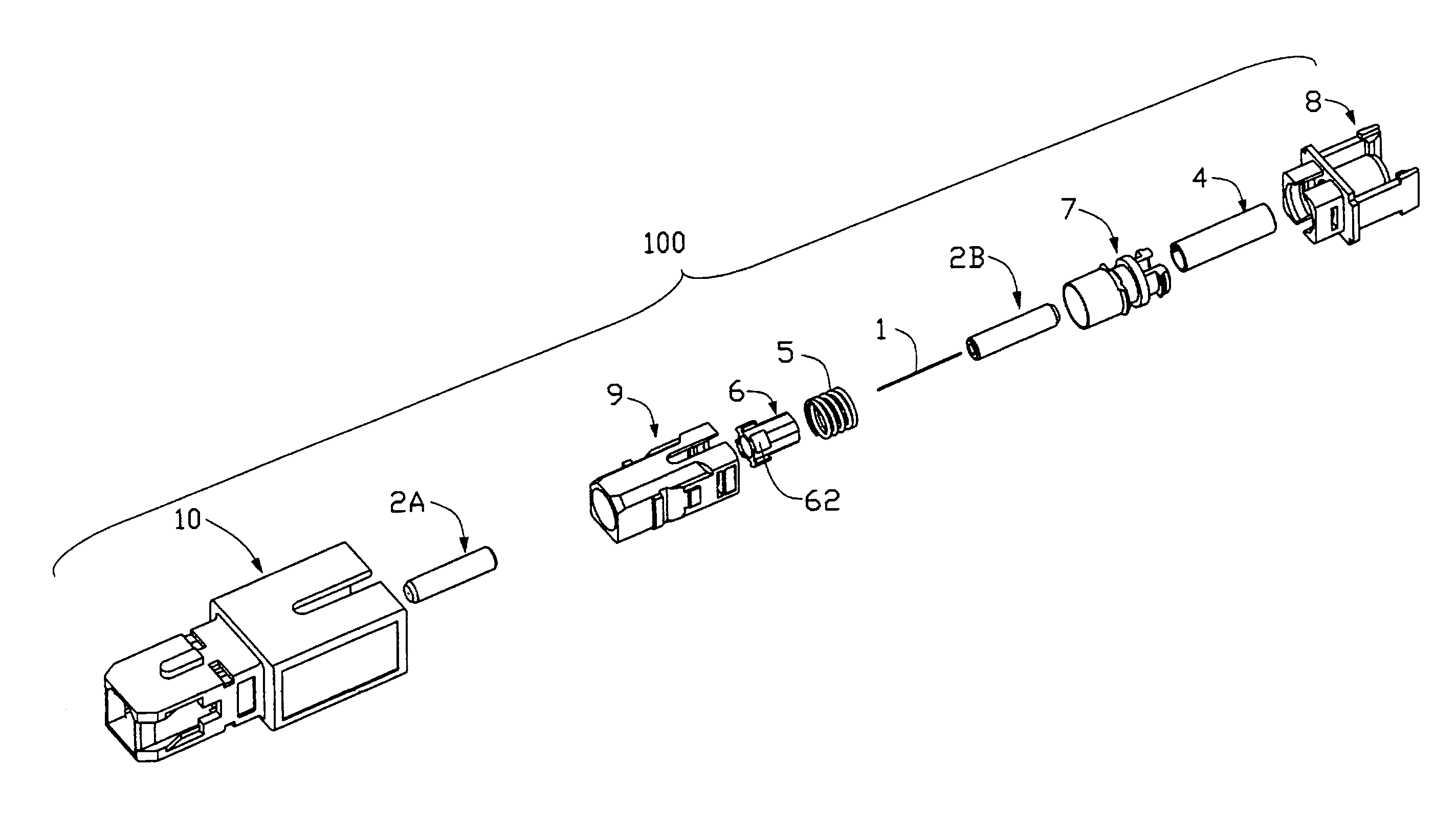
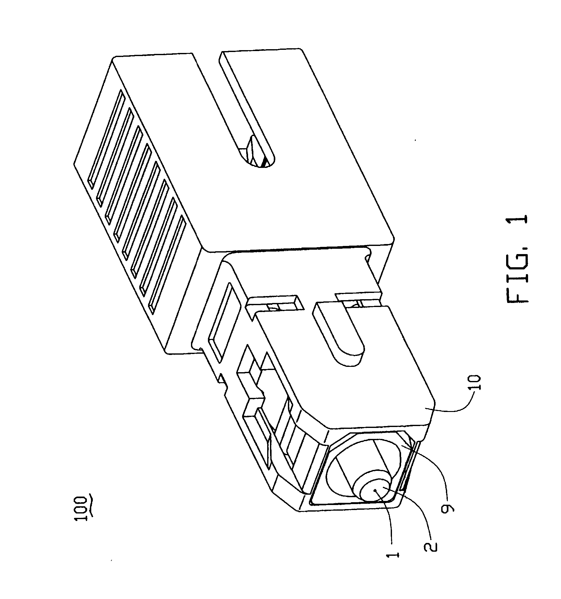
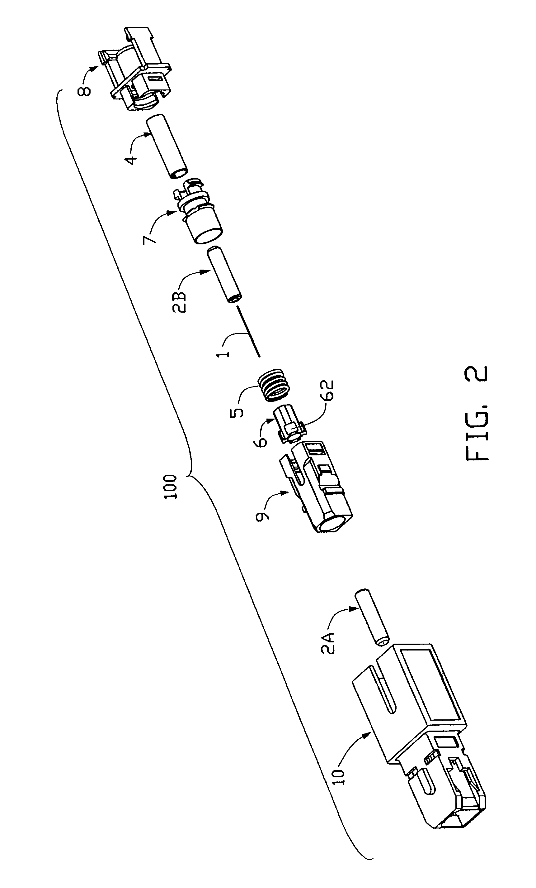
[0023] Referring to FIG. 2, an optical attenuator 100 comprises an optical fiber 1, two ferrules 2A, 2B, an alignment sleeve 4, a spring 5, a flange 6, an interconnection housing 7, a latch 8, a plug housing 9 and a cover 10.

[0024] The optical fiber 1 is doped with cobalt, or similar elements, and can attenuate by a predetermined amount of a light beam propagating therethrough. The ferrules 2A and 2B are round rods, and each of them defines a through hole (not labeled) longitudinally therethrough for retaining the optical fiber 1. The flange 6 comprises four projections 62 formed on a front end thereof.

[0025] Referring to FIG. 3, the interconnection housing 7 comprises a tubular section 70 and a flanged section 77 located rearward of the tubular section 70. A circumferential first flange 71, a circumferential second flange 72 and a circumfere...


PUM


Abstract

An optical attenuator (100) has an optical attenuation fiber (1) doped with cobalt. Two ferrules (2A), (2B) retain the optical attenuation fiber therein. Two butting ends of the ferrules are enclosed in a flange (6), which is received in a front end of an interconnection housing (7). An alignment sleeve (4) retains a rear end of the rear ferrule and is enclosed in a rear end of the interconnection housing. A latch (8) engages with the rear end of the interconnection housing. A plug housing (9) engages with the front end of the interconnection housing. A cover (10) then attaches over all the aforesaid components. A front end of the front ferrule is exposed outside the cover, for connecting with a complementary optical connector.

Description

[0001] 1. Field of the Invention[0002] The present invention relates to optical attenuators, and more particularly to fixed optical attenuators used in optical systems.[0003] 2. Description of Related Prior Art[0004] Optical attenuators are widely used in optical transmission systems and optical networks. Optical attenuators are passive optical components that can reduce optical power propagating in optical fibers, and may be categorized as either fixed or variable attenuators.[0005] FIG. 9 is a cross-sectional view of a fixed optical attenuator known in the prior art. A through hole 13 is bored in the central portion of a cylindrical ferrule 14. An optical attenuation fiber 15 is inserted into the through hole 13 and is glued to the inner surface thereof. Further, a flange 18 is fixed onto the circumferential surface of the ferrule 14. This flange 18 serves to limit the movement of the ferrule within the optical attenuator in the axial and circumferential directions.[0006] In FIG. ...

Claims


Application Information

Patent Timeline
Patent Type & Authority Applications(United States)
IPC IPC(8): G02B6/26G02B6/38
CPCG02B6/266G02B6/3821G02B6/3874G02B6/3846G02B6/3825
Inventor CHANG, YAO-HAO
Owner GOOGLE LLC
Why Eureka
Try Eureka