

Paint container
a paint container and container body technology, applied in the field of paint containers, can solve the problems of affecting the appearance of the container, etc., and achieves the effect of reducing the difficulty of subsequent removal of the lid
- Summary
- Abstract
- Description
- Claims
- Application Information
AI Technical Summary
Benefits of technology
Problems solved by technology
Method used
Image

Examples
Embodiment Construction
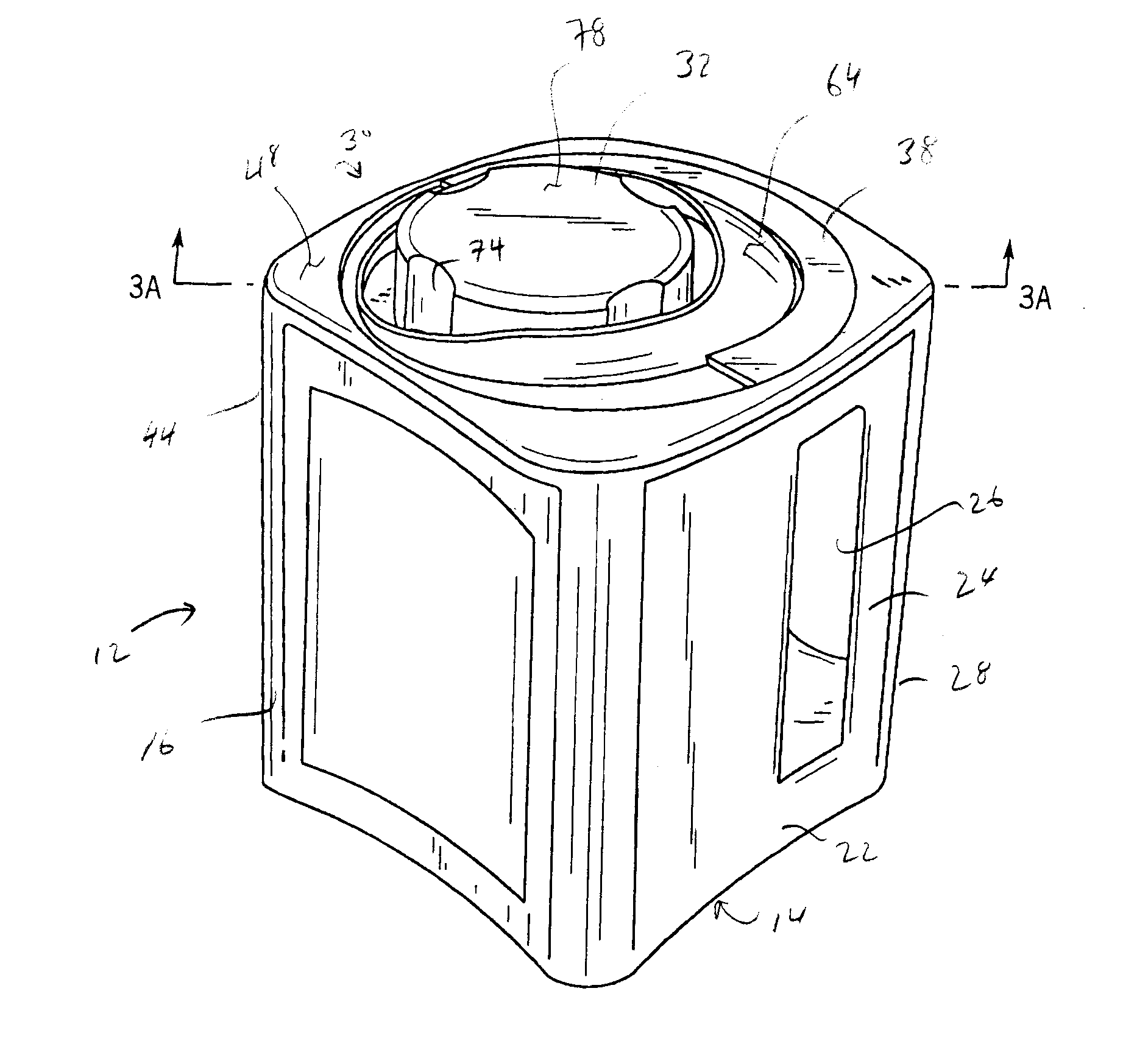
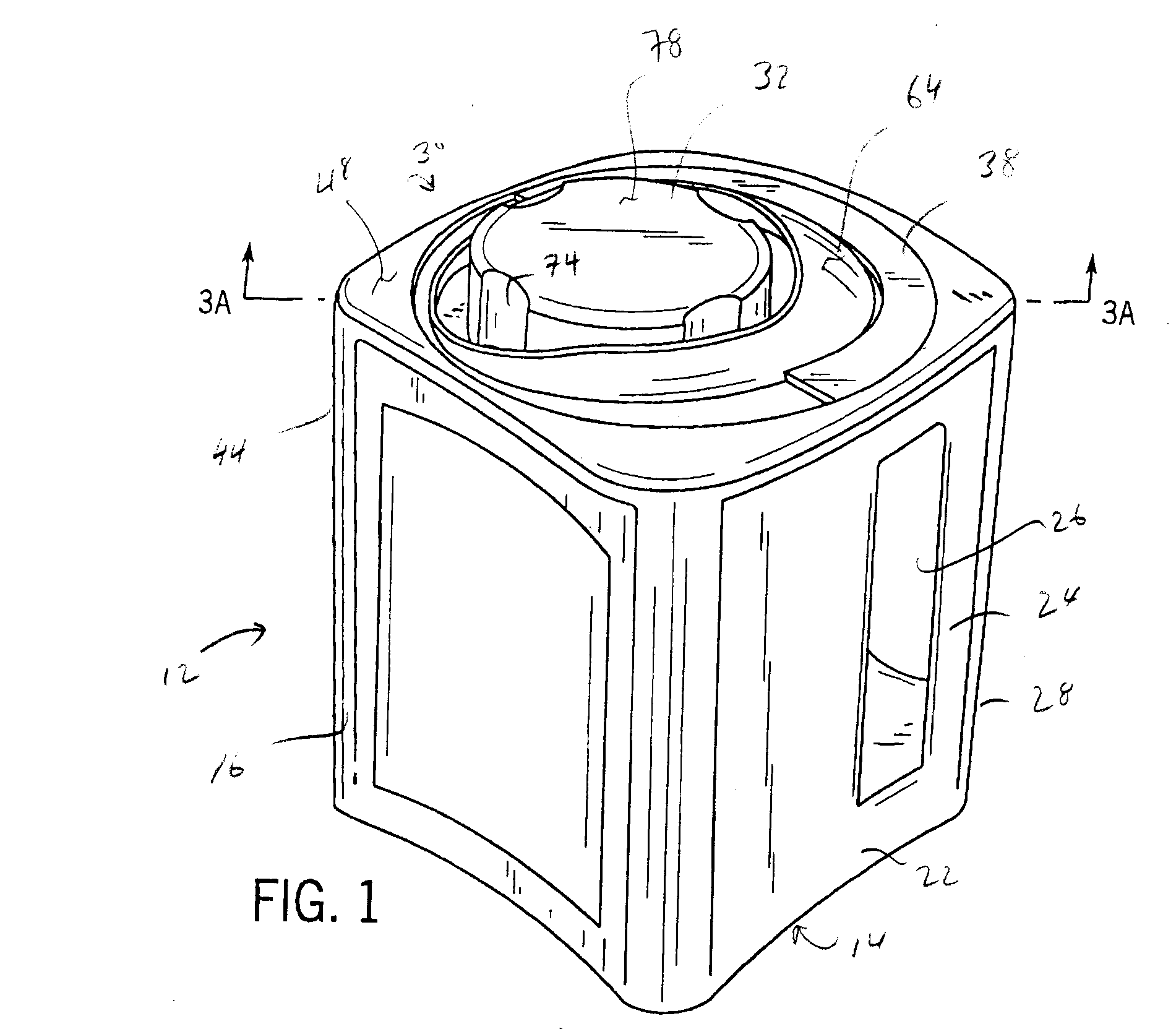
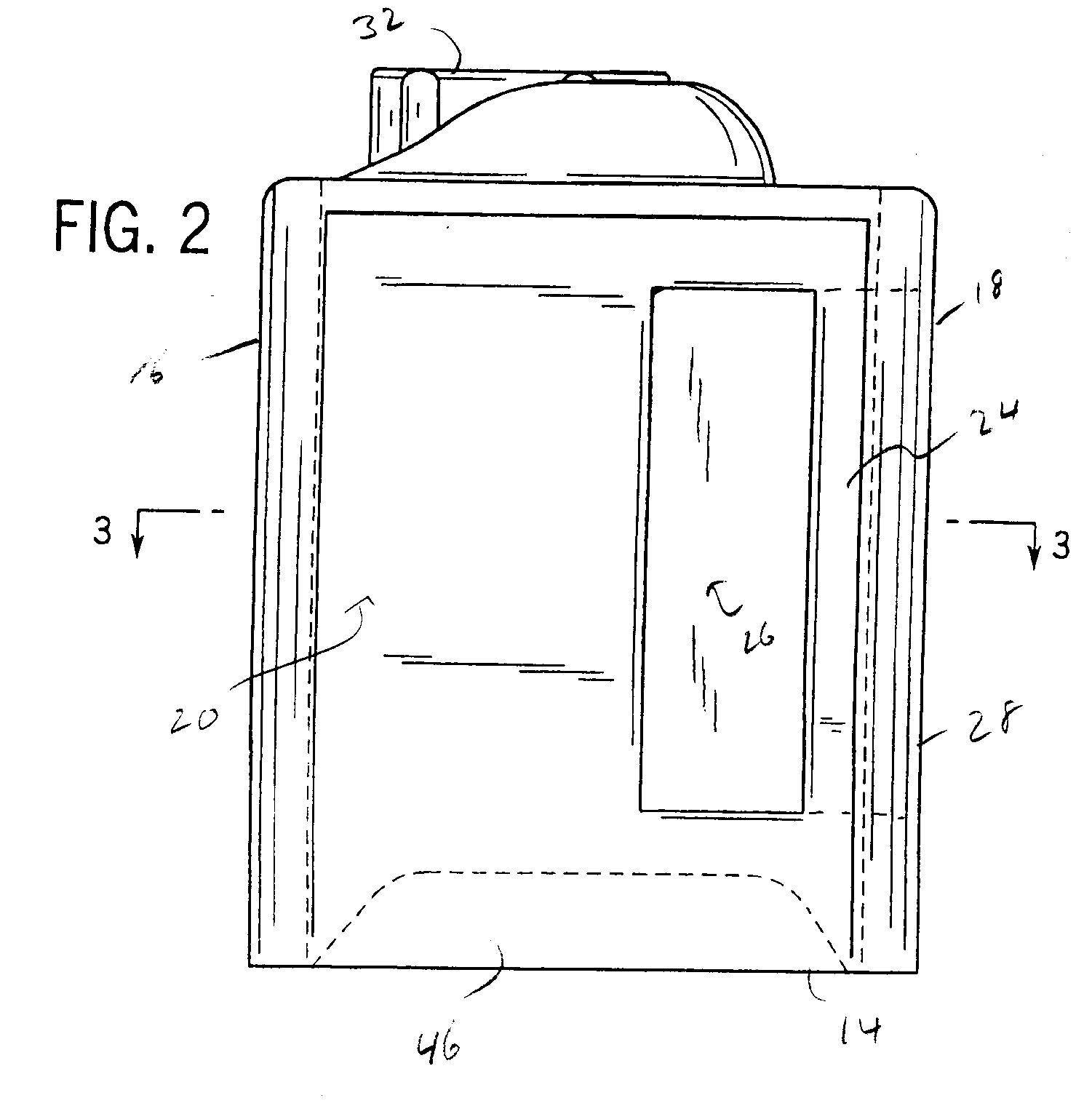
[0041] Referring to FIGS. 1-6, a paint container 10 includes a body member 12 having a bottom 14, a front wall 16, a back wall 18 and a pair of opposing side walls 20, 22. Body member 12 further includes a handle 24 formed by an aperture 26 located proximate to a first corner 28. Paint container 10 further includes a top region 30 integrally formed with the body member 12. In one embodiment paint container 10 is formed from a plastic material that is injection molded, blow molded, or injection blow molded. However, the paint container may formed from other methods known in the art. Alternatively top region 30 may be attached to the body member 12 with either a mechanical connection, interference fit or chemical bond.
[0042] A cap or cover 32 is threadably secured to an attachment or land 34 of the top region 30. As show in FIG. 5 top region 30 includes a spout 36 from which the paint stored within the container 10 is poured. The spout 36 is covered by cap 32 when the cap 32 is thread...
PUM
 Abstract
Description
Claims
Application Information