Polygon-based bioptical POS scanning system employing dual independent optics platforms disposed beneath horizontal and vertical scanning windows

a scanning system and polygon technology, applied in the field of laser scanners, can solve the problems of inability to optimize the laser scanning pattern of such prior art bioptical laser scanning systems in terms of scanning coverage and performance, and the general aggressiveness of prior art bioptical scanning systems over conventional single scanning window systems, etc., to achieve the effect of improving the dynamic rang

Inactive Publication Date: 2003-06-05
METROLOGIC INSTR
View PDF37 Cites 41 Cited by
  • Summary
  • Abstract
  • Description
  • Claims
  • Application Information

AI Technical Summary

Benefits of technology

[0023] Accordingly, a primary object of the present invention is to provide a novel bioptical laser scanning system which is free of the shortcomings and drawbacks of prior art bioptical laser scanning systems and methodologies.
[0034] A further object of the present invention is to provide such a bioptical laser scanning system, in which an independent signal processing channel is provided for each laser diode and light collection / detection subsystem in order to improve the signal processing speed of the system.
[0036] A further object of the present invention is to provide a bioptical laser scanning system that provides improved scan coverage over the volume disposed between the two scanning windows of the system.
[0053] In another aspect of the present invention, it is a primary objective to provide an improved laser scanning system, wherein scan data signals produced therewithin are processed so that the effects of thermal and paper noise encountered within the system are significantly mitigated.
[0054] Another object of the present invention is to provide an improved laser scanning system having a scan data signal processor with improved dynamic range.
[0116] FIG. 6 is an exemplary timing scheme for controlling the bioptical laser scanner of the illustrative embodiment to cyclically generate a complex omni-directional 3-D laser scanning pattern from both the bottom and side-scanning windows 16 and 18 thereof during the revolutions of the scanning polygonal mirrors PM1 and PM2; in this exemplary timing scheme, four sets of scan plane groups (4*[GH1 . . . GH7]) are produced by stations HST1 and HST2 during each revolution of the polygonal mirror PM1 concurrently with two sets of scan plane groups (2*[GV1 . . . GV14]) produced by station VST1 during a single revolution of the polygonal mirror PM2; this complex omni-directional scanning pattern is graphically illustrated in FIGS. 3A through 5P2; the 3-D laser scanning pattern of the illustrative embodiment consists of 68 different laser scanning planes, which cooperate in order to generate a plurality of quasi-orthogonal laser scanning patterns within the 3-D scanning volume of the system, thereby enabling true omnidirectional scanning of bar code symbols.

Problems solved by technology

In general, prior art bioptical laser scanning systems are generally more aggressive that conventional single scanning window systems.
While prior art bioptical scanning systems represent a technological advance over most single scanning window system, prior art bioptical scanning systems in general suffered from various shortcomings and drawbacks.
In particular, the laser scanning patterns of such prior art bioptical laser scanning systems are not optimized in terms of scanning coverage and performance, and are generally expensive to manufacture by virtue of the large number of optical components presently required to constructed such laser scanning systems.
Moreover, the performance of such aggressive laser scanning systems (in scanning a bar code symbol and accurately produce digital scan data signals representative of a scanned bar code symbol) is susceptible to noise, including ambient noise, thermal noise and paper noise.
However, as a result of such noise components, the transitions from the first signal level to the second signal level and vice versa are not perfectly sharp, or instantaneous.
Consequently, it is difficult to determine the exact instant that each binary signal level transition occurs in detected analog scan data signal.
As a practical matter, it is not possible in most instances to produce analog scan data signals with precisely-defined signal level transitions.
Consequently, the gating signal mechanism disclosed in U.S. Pat. No. 4,000,397 allows "false" second-derivative zero-crossing signals to be passed onto the second-derivative zero-crossing detector thereof, thereby producing erroneous binary signal levels at the output stage of this prior art signal processor.
This can result in significant errors during bar code symbol decoding operations, causing objects to be incorrectly identified and / or erroneous data to be entered into a host system.
WO 97 / 22945 published on Jun. 26, 1997, Applicants' have observed that the effects of paper / substrate noise are greatly amplified when scanning bar code symbols in the near focal zone(s), thereby causing a significant decrease in overall system performance.
While this technique has allowed prior art scanning systems to scan bar codes in the far focal zones of the system, it has in no way addressed or provided a solution to the problem of increased paper / substrate noise encountered when scanning bar code symbols in the near focal zones of such laser scanning systems.
Moreover, although filters and signal thresholding devices are useful for rejecting noise components in the analog scan signal, such devices also limit the scan resolution of the system, potentially rendering the system incapable of reading low contrast and high resolution bar code symbols on surfaces placed in the scanning field.

Method used


Image

  • Polygon-based bioptical POS scanning system employing dual independent optics platforms disposed beneath horizontal and vertical scanning windows
  • Polygon-based bioptical POS scanning system employing dual independent optics platforms disposed beneath horizontal and vertical scanning windows
  • Polygon-based bioptical POS scanning system employing dual independent optics platforms disposed beneath horizontal and vertical scanning windows

Examples


Embodiment Construction

[0129] Referring to the figures in the accompanying Drawings, the various illustrative embodiments of the bioptical laser scanner of the present invention will be described in great detail.

[0130] In the illustrative embodiments, the apparatus of the present invention is realized in the form of an automatic code symbol reading system having a high-speed bioptical laser scanning mechanism as well as a scan data processor for decode processing scan data signals produced thereby. However, for the sake of convenience of expression, the term "bioptical laser scanner" shall be used hereinafter to denote the bar code symbol reading system which employs the bioptical laser scanning mechanism of the present invention.

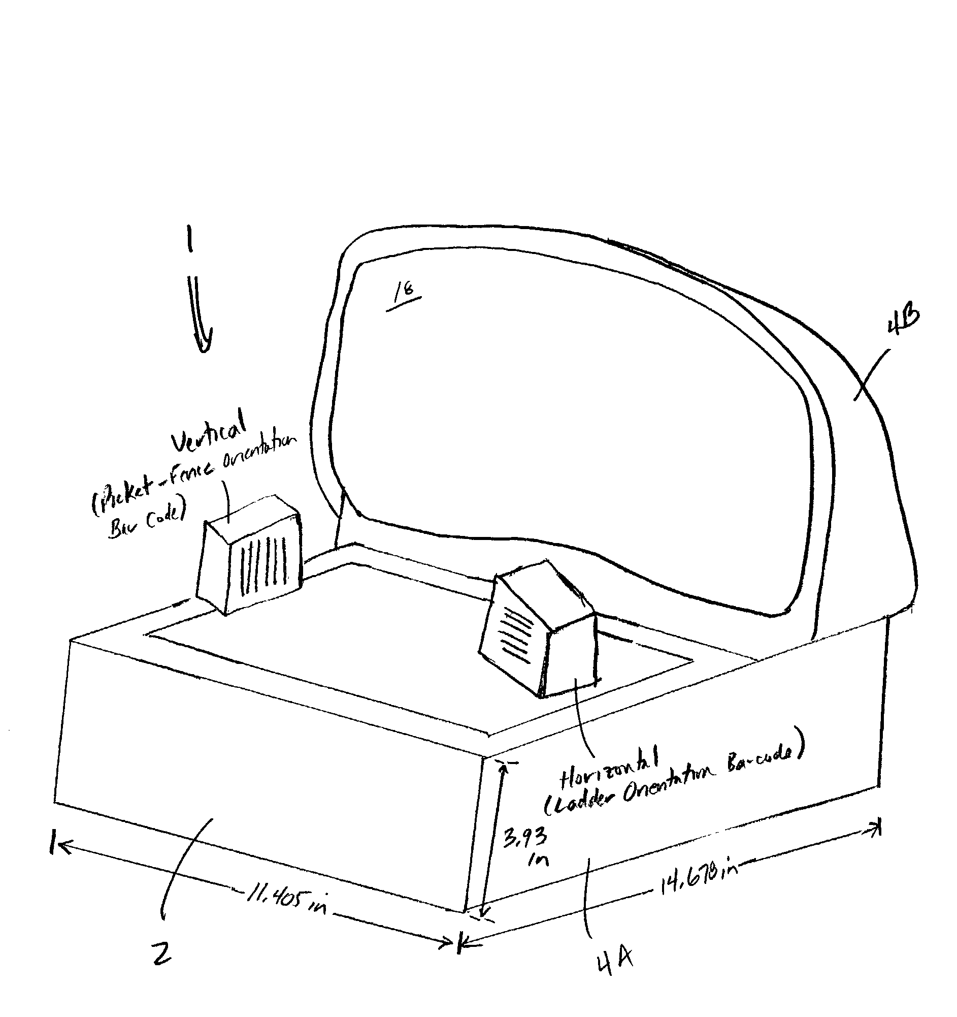
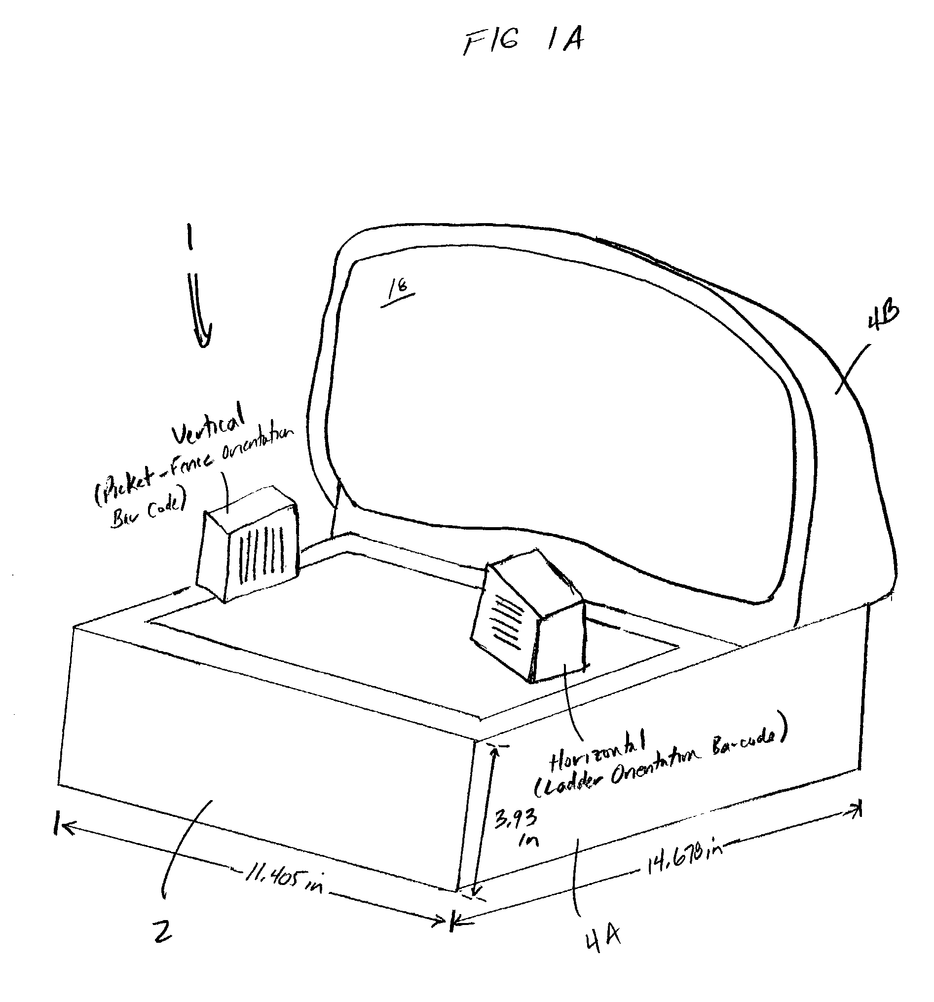
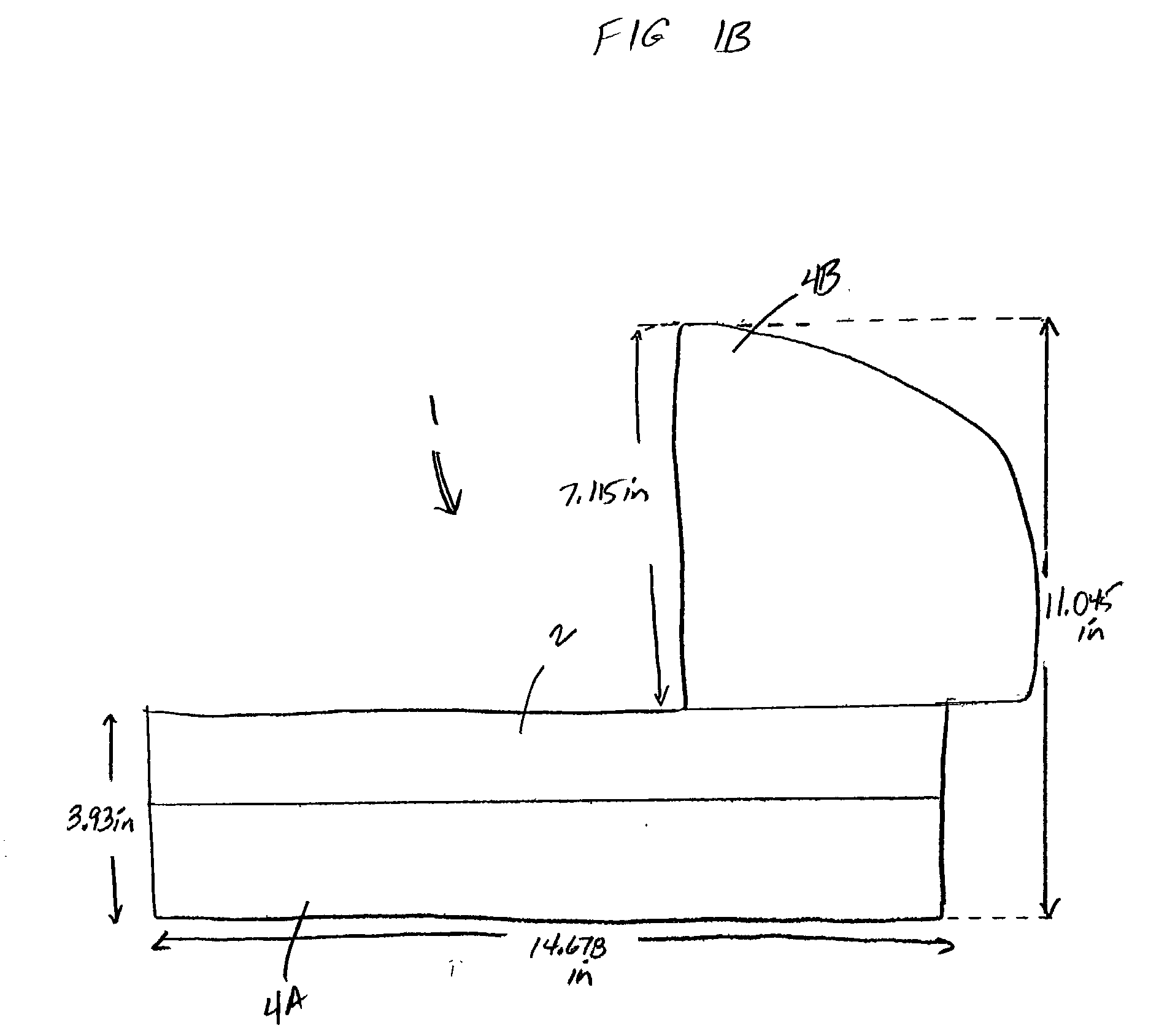
[0131] As shown in FIGS. 1A through 1G, the bioptical laser scanner 1 of the illustrative embodiment of the present invention has a compact housing 2 having a first housing portion 4A and a second housing portion 4B which projects from one end of the first housing portion 4A in a...


PUM


Abstract

A bioptical laser scanning system employing a plurality of laser scanning stations about a two independently controlled rotating polygonal mirrors. The system has an ultra-compact construction, ideally suited for space-constrained retail scanning environments, and generates a 3-D omnidirectional laser scanning pattern between the bottom and side-scanning windows during system operation. The laser scanning pattern of the present invention comprises a complex of quasi-orthogonal laser scanning planes, including a plurality of substantially-vertical laser scanning planes for reading bar code symbols having bar code elements (i.e. ladder type bar code symbols) that are oriented substantially horizontal with respect to the bottom-scanning window, and a plurality of substantially-horizontal laser scanning planes for reading bar code symbols having bar code elements (i.e. picket-fence type bar code symbols) that are oriented substantially vertical with respect to the bottom-scanning window.

Description

CROSS-REFERENCE TO RELATED U.S. APPLICATIONS[0001] This is a Continuation-in-Part of copending application Ser. No. 09 / 551,887 entitled "Bioptical Holographic Laser Scanning System" filed Apr. 18, 2000, said application being owned by Assignee, Metrologic Instruments, Inc., of Blackwood, N.J., and incorporated herein by reference as if fully set forth herein.[0002] 1. Field of Invention[0003] The present invention relates generally to laser scanners of ultra-compact design capable of reading bar code symbols in point-of-sale (POS) and other demanding scanning environments.[0004] 2. Brief Description of the Prior Art[0005] The use of bar code symbols for product and article identification is well known in the art. Presently, various types of bar code symbol scanners have been developed. In general, these bar code symbol readers can be classified into two distinct classes.[0006] The first class of bar code symbol reader simultaneously illuminates all of the bars and spaces of a bar co...

Claims


Application Information

Patent Timeline
Patent Type & Authority Applications(United States)
IPC IPC(8): G06K7/10
CPCG02B26/10G07G1/0054G06K7/10G06K7/10564G06K7/10584G06K7/10594G06K7/10603G06K7/10663G06K7/10673G06K7/10693G06K7/10702G06K7/10792G06K7/10801G06K7/10811G06K7/10851G06K7/10861G06K7/10871G06K7/10881G06K7/10891G06K7/109G06K7/14G06K17/0022G06K2207/1012G06K2207/1013G06K2207/1016G06K2207/1017G06K2207/1018G07G1/0045G02B26/106
Inventor GOOD, TIMOTHY
Owner METROLOGIC INSTR
Why Eureka
Try Eureka