Optical switch having routing indicators

a technology of optical switches and routing indicators, applied in the field of optical switches, can solve the problems of optical switches liable to be improperly operated by operators, and the actual light routing status of such optical switches is not apparent to operators

Inactive Publication Date: 2003-06-12
HON HAI PRECISION IND CO LTD
View PDF5 Cites 4 Cited by
  • Summary
  • Abstract
  • Description
  • Claims
  • Application Information

AI Technical Summary

Problems solved by technology

However, the actual light routing status of the light beams of such optical switch is not apparent to an operator.
Therefore, the optical switch is liable to be improperly operated by the operator.

Method used


Image

  • Optical switch having routing indicators
  • Optical switch having routing indicators
  • Optical switch having routing indicators

Examples


Embodiment Construction

[0017] Reference will now be made to the drawings to describe the present invention in detail.

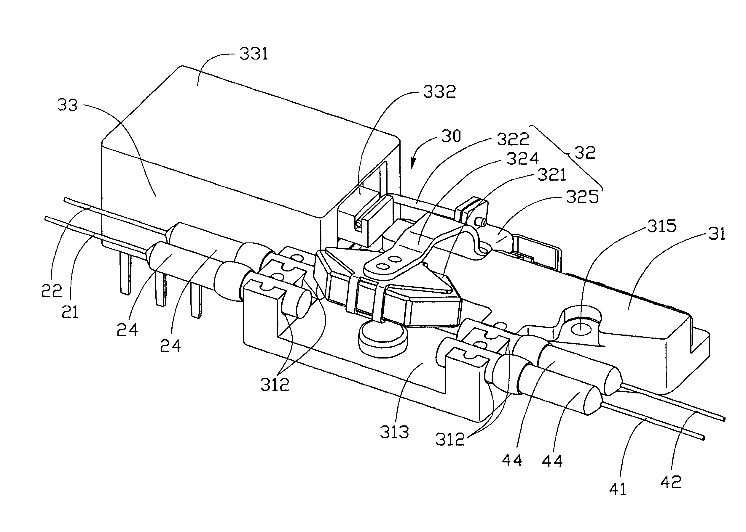
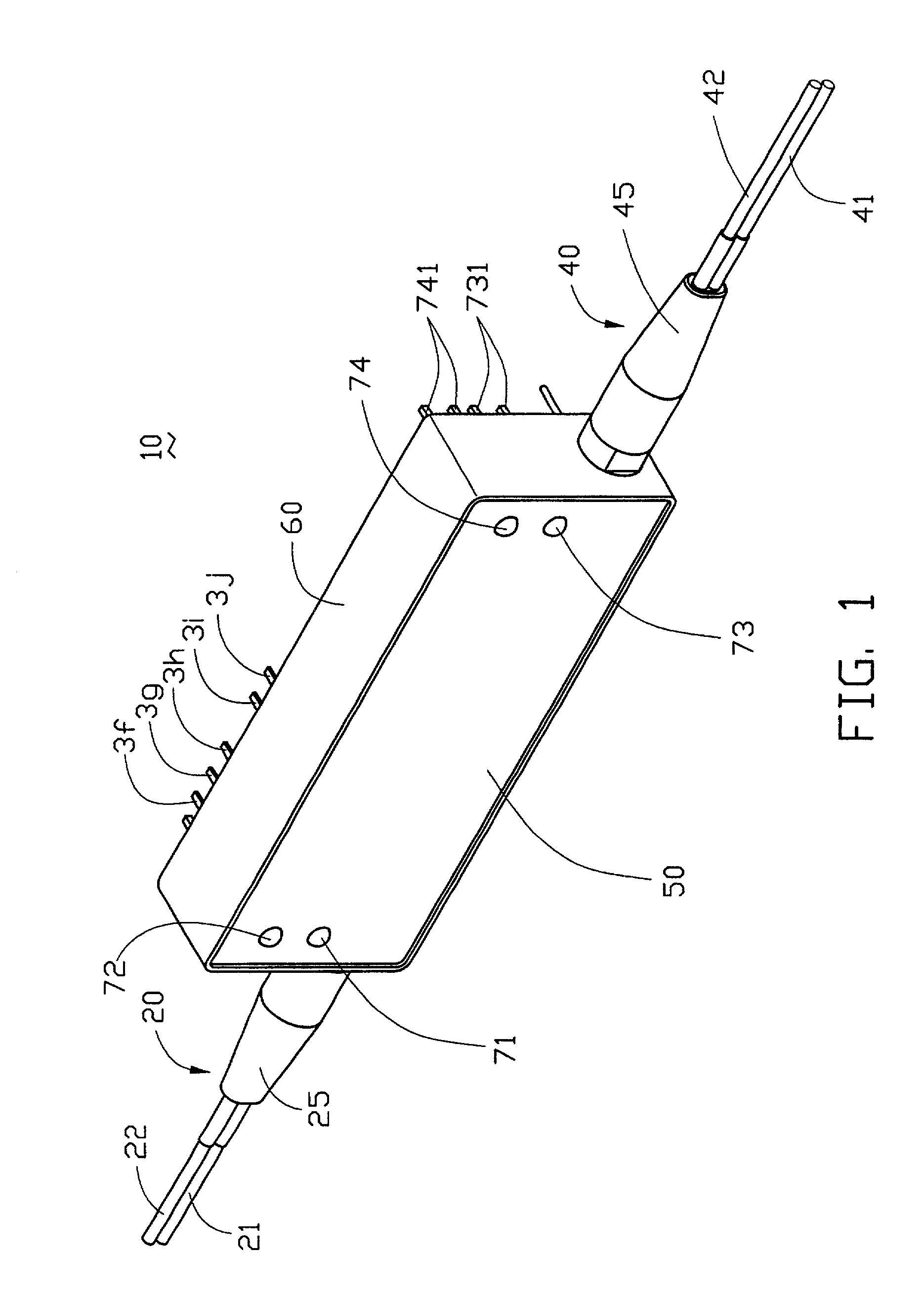
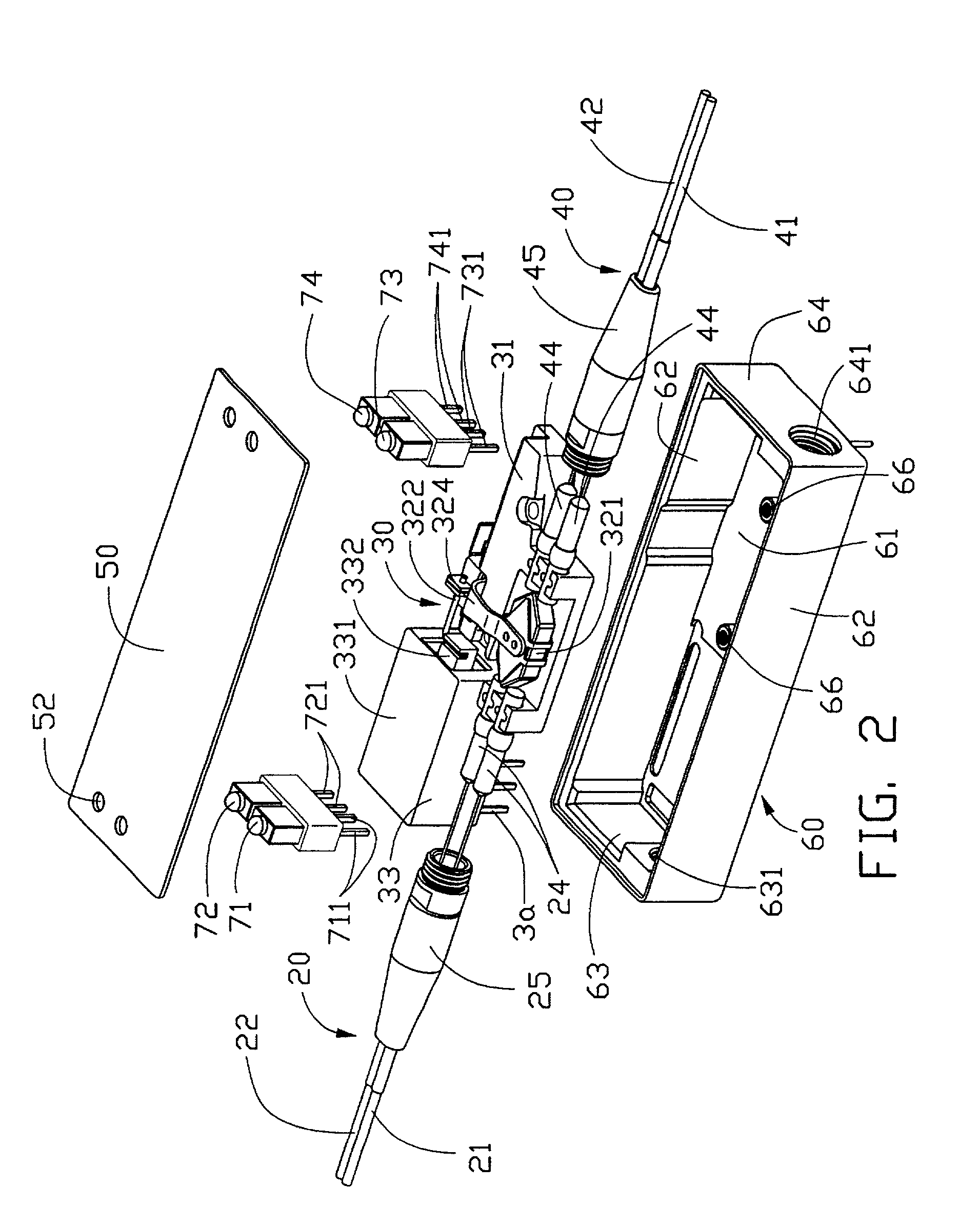
[0018] Referring to FIGS. 1 and 2, an optical switch 10 in accordance with the present invention comprises an input assembly 20, an output assembly 40, a path-switching assembly 30, first and second input indicators 71, 72, first and second output indicators 73, 74, an upper cover 50 and a lower cover 60. The input assembly 20 is attached to a front portion of the path-switching assembly 30, and the output assembly 40 is attached to a rear portion of the path-switching assembly 30.

[0019] The input assembly 20 comprises first and second input optical fibers 21, 22, two collimators 24 (see FIG. 3), and a first strain relief boot 25. Each input optical fiber 21, 22 is attached to one end of a corresponding collimator 24. The first strain relief boot 25 retains the input optical fibers 21, 22 and portions of the collimators 24 therein.

[0020] The output assembly 40 comprises first and second out...


PUM


Abstract

An optical switch (10) includes two input optical fibers (21, 22) for inputting light beams, two output optical fibers (41, 42) for receiving the light beams, a path-switching assembly (30) having a prism (321) for switching paths of the light beams, a relay (33) having a controlling circuit for controlling the path-switching assembly, two input indicators (71, 72), and two output indicators (73, 74). The path-switching assembly has a first operative state in which the prism is moved out of a path of the light beams, and a second operative state in which the prism is moved into the path. The input indicators are single color LEDs that can respectively display orange and green. The output indicators both are double color LEDs, and each can display orange and green. The output indicators instantly change color upon a change in the status of light routing of the optical switch.

Description

[0001] 1. Field of the Invention[0002] The present invention relates to optical switches, and particularly to an optical switch having light-emitting diodes (LEDs) as light routing indicators.[0003] 2. Description of Related Art[0004] Optical switches are required in numerous fiber optic systems. For example, optical switches redirect light from one optical fiber to another. Optical switches are classified into mechanical and non-mechanical switches. In mechanical switches, the switching function is generally performed by mechanical means.[0005] U.S. Pat. No. 4,322,126 discloses a 2.times.2 mechanical optical switch. The mechanical optical switch has a prism, a switching means for controlling the prism, first and second input optical fibers, and first and second output optical fibers. The prism is a hexagonal prism for exchanging optical paths of two initially parallel light beams transmitted from the input optical fibers. The input and output optical fibers are respectively attache...

Claims


Application Information

Patent Timeline
Patent Type & Authority Applications(United States)
IPC IPC(8): G02B6/35
CPCG02B6/3528G02B6/3586G02B6/3582G02B6/3546
Inventor CHANG, YAO-HAO
Owner HON HAI PRECISION IND CO LTD
Why Eureka
Try Eureka