Ultrasonic transceiver and ultrasonic clearance sonar using the same

a technology of ultrasonic transceiver and ultrasonic clearance sonar, which is applied in the direction of instruments, device details, and piezoelectric/electrostrictive device details, etc., can solve the problems of inaccurate ultrasonic clearance sonar judgment, unstable reverberation waveform, and inability to accurately judge the abnormality of ultrasonic transceiver by using reverberation waveform

Inactive Publication Date: 2003-07-03
DENSO CORP +1
View PDF6 Cites 73 Cited by
  • Summary
  • Abstract
  • Description
  • Claims
  • Application Information

AI Technical Summary

Problems solved by technology

The conventional method of detecting the trouble of the ultrasonic transceiver by using the reverberation waveform cannot accurately judge that the ultrasonic transceiver is abnormal because of the oscillation of the waveform.
The oscillation of the tubular side wall of the synthesized oscillations causes the

Method used


Image

  • Ultrasonic transceiver and ultrasonic clearance sonar using the same
  • Ultrasonic transceiver and ultrasonic clearance sonar using the same
  • Ultrasonic transceiver and ultrasonic clearance sonar using the same

Examples


first embodiment

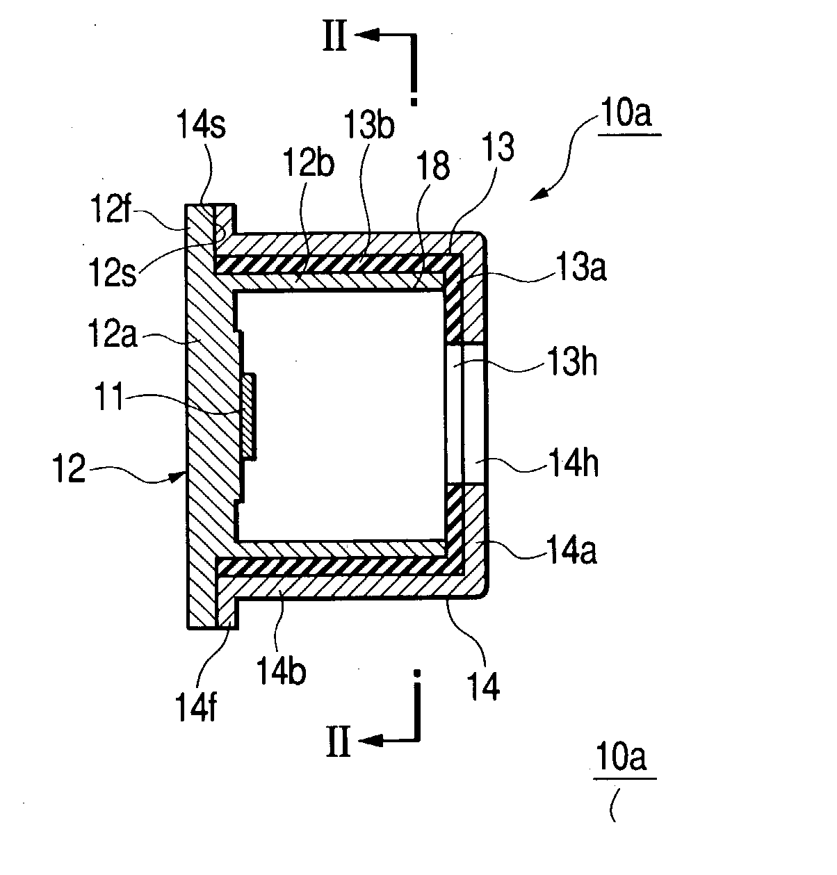
[0032] (First Embodiment)

[0033] A first embodiment of the present invention will be described hereinafter with reference to the accompanying drawings.

[0034] FIG. 1A is a longitudinal cross sectional view of an ultrasonic transceiver in the axial direction thereof according to the first embodiment, and FIG. 1B is a lateral cross sectional view of the ultrasonic transceiver in the radial direction thereof.

[0035] In each of FIGS. 1A and 1B, a state of the ultrasonic transceiver, before providing therefor a sponge and a resin layer described hereinafter, is shown.

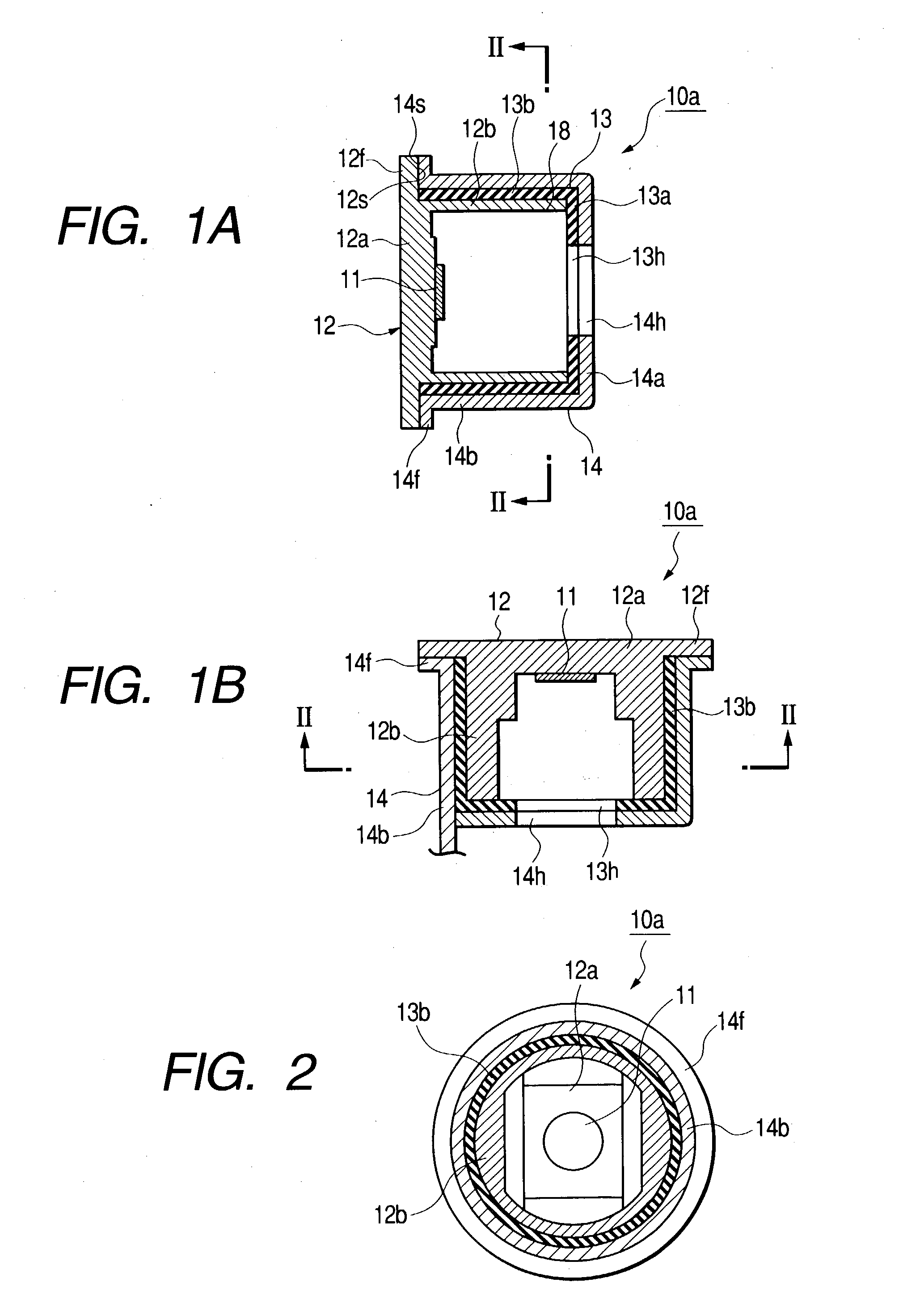
[0036] In addition, FIG. 2 is a cross sectional view of the ultrasonic transceiver taken on line II-II of each of FIGS. 1A and 1B.

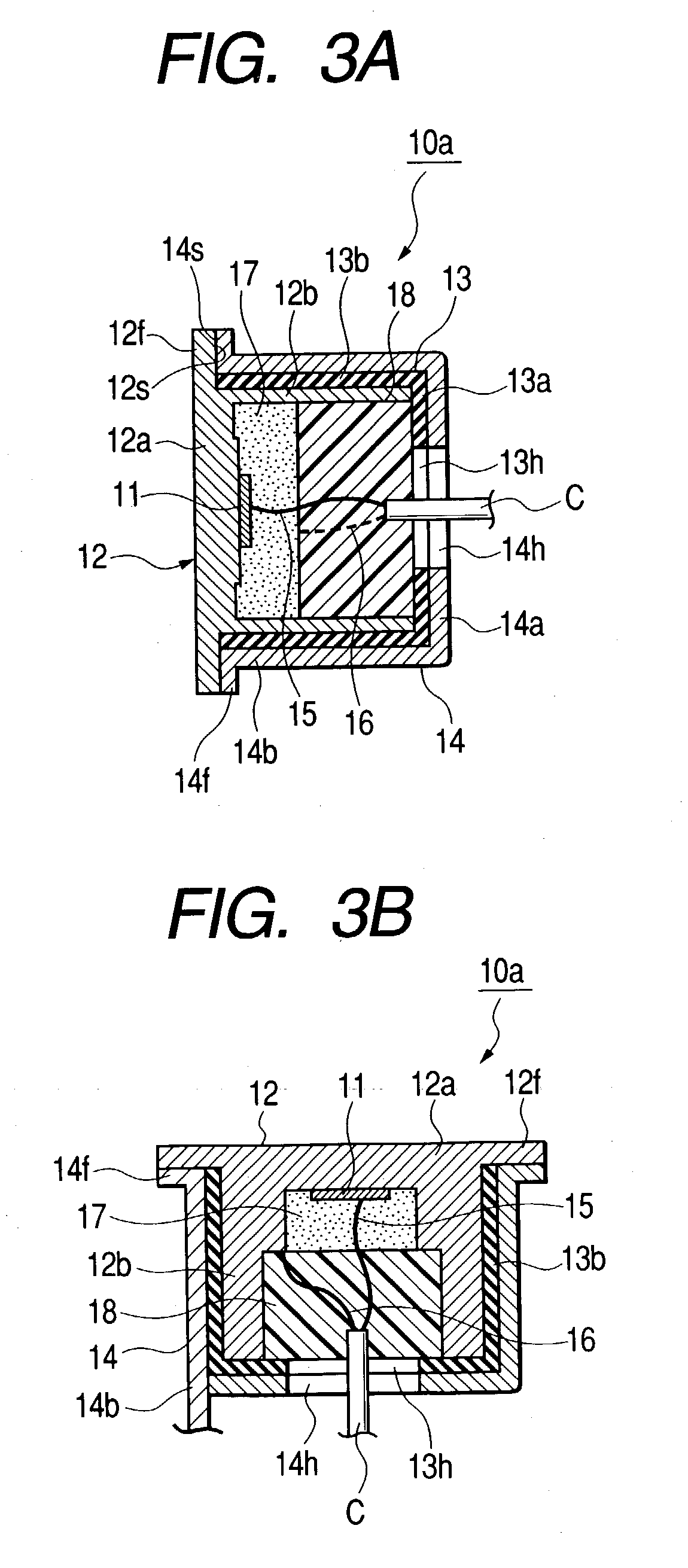
[0037] FIG. 3A is a longitudinal cross sectional view of the ultrasonic transceiver in the axial direction thereof, for which the sponge and the resin layer are already provided, and FIG. 3B is a lateral cross sectional view of the ultrasonic transceiver shown in FIG. 3A in the radial direction there...

second embodiment

[0086] (Second Embodiment)

[0087] FIG. 7 is a longitudinal cross sectional view showing a state that an ultrasonic transceiver 10b according to a second embodiment is installed on a vehicle.

[0088] In FIG. 7, elements of the ultrasonic transceiver 10b which are the same as those of the ultrasonic transceiver 10a are assigned to the same reference numerals thereof, omitting explanations of the elements of the ultrasonic transceiver 10b.

[0089] The ultrasonic transceiver 10b according to the second embodiment has an inner housing 50. The inner housing 50 is provided with a cylindrical plate-like bottom portion (transmitting wall) 50a on its inner end surface of which the piezoelectric member 11 is mounted. The inner housing 50 is also provided with a first cylindrical tubular side wall 50b extending from the inner end surface of the peripheral portion of the transmitting wall 50a in the axial direction.

[0090] The inner housing 50 is further provided with a first flange portion 51 formed ...

third embodiment

[0103] (Third Embodiment)

[0104] FIG. 8 is a longitudinal cross sectional view showing a state that an ultrasonic transceiver 10c according to a third embodiment is installed on a vehicle.

[0105] In FIG. 8, elements of the ultrasonic transceiver 10c which are the same as those of the ultrasonic transceiver 10a and / or the ultrasonic transceiver 10b are assigned to the same reference numerals thereof, omitting explanations of the elements of the ultrasonic transceiver 10c.

[0106] The ultrasonic transceiver 10c according to the third embodiment comprises an inner housing 60 which is provided with a cylindrical plate-like bottom portion (transmitting wall) 60a on its inner end surface of which the piezoelectric member 11 is mounted. The inner housing 60 is also provided with a first cylindrical tubular side wall 60b extending from the inner end surface of the peripheral portion of the transmitting wall 60a in the axial direction.

[0107] The ultrasonic transceiver 10c is configured in that, ...


PUM


Abstract

In an ultrasonic transceiver, an inner housing has a bottom portion, a first tubular side wall extending from one end surface of the bottom portion and a first flange portion formed on an outer peripheral portion of the first tubular side wall. The bottom portion and first tubular side wall provide a tubular cavity formed therebetween, and the piezoelectric member is mounted on the one end surface of the bottom portion in the tubular cavity. An outer housing has a second tubular side wall coaxially arranged around the outer peripheral portion of the first tubular side wall with a predetermined gap therebetween. The second tubular side wall is provided with one end portion which is opposite to one end surface of the first flange portion and contacted thereto. A first absorption member is inserted in the gap between the first tubular side wall and the second tubular side wall.

Description

[0001] 1. Field of the Invention[0002] The present invention relates to an ultrasonic transceiver which is installed to, for example, a vehicle such as an automobile or the like and adapted to detect that the vehicle is near to obstacles when the vehicle is parked or turned, and an ultrasonic clearance sonar using the ultrasonic transceiver.[0003] 2. Description of the Related Art[0004] An ultrasonic clearance sonar can announce an alert to draw driver's attention to obstacles around the vehicle in accordance with each distance between the vehicle and each obstacle.[0005] The ultrasonic clearance sonar has an ultrasonic transceiver also called to as "microphone" and is configured to cause the transceiver to transmit ultrasonic waves to a space around the vehicle, and measure each distance from the vehicle (ultrasonic transceiver) to each obstacle on the basis of each time for which each echo, that is, each ultrasonic wave reflected from each obstacle is returned to the ultrasonic tr...

Claims


Application Information

Patent Timeline
IPC IPC(8): G01S15/931H04R1/44G01S7/52G01S7/521G10K9/122H04R17/00
CPCG01S7/52004G01S7/521G01S2015/938G01S2013/9389G10K9/122G01S15/931G01S2013/93275
Inventor MITSUOKA, HIDEOKANI, HIROYUKISATO, YOSHIHISATAKEICHI, MASAKAZUODA, KIYONARIMATSUOKA, HISANAGAMATSUURA, MICHIHIRO
Owner DENSO CORP
Why Eureka
Try Eureka