Orthodontic retainer elements

a retainer and orthodontic technology, applied in dentistry, medical science, dental tools, etc., can solve the problems of inaccurate retainer plates, easy to break easily, limited tooth setting must be counted, etc., to achieve strong bonding, greater together pulling force, and stable effect on each other

Inactive Publication Date: 2003-07-03
AMUNDSEN OLE CHRISTIAN
View PDF6 Cites 20 Cited by
  • Summary
  • Abstract
  • Description
  • Claims
  • Application Information

AI Technical Summary

Benefits of technology

0023] Common for all such different configurations of the retainer approximal surfaces of pairs of elements is that because of their complementary geometric configurations they cooperate in their positions of use in the way that they mutually support, possibly lock, each other and thereby have a stabilizing effect on each other. If, during the retention period, one tooth seeks to divert from the desired tooth position, either in that the tooth seeks to rotate about its own longitudinal axis and/or that the tooth rotates about its anchoring area in the connective tissue in the tooth gum, the adjacent tooth will seek to resist this through the pair of retainer elements. In addition such undesired tooth movements can be counteracted in that cooperating retainer approximal surfaces are formed and/or adapted with a desired degree of roughness, so that the friction that occurs when the retainer approximal surfaces are forced against one another, counteracts this diversion motion. This counteracting effect is further increased in that all the teeth in a retention segment can be provided successively and in pairs with cooperating pairs of retainer elements, so that the retention segment is thereby stabilized by means of several such pairs of retainer elements. Therefore, every tooth in the retention segment is provided with two retainer elements, one element thereof at each of the two tooth approximal surfaces of the tooth, the connection between the two retainer elements being formed, in terms of strength, by the tooth itself. Thereby, these two retainer elements do not form a pair of complementarily cooperating retainer elements. On the contrary, each of the two elements is arranged to a complementary and cooperating element on an adjacent tooth.
0024] The positioning of a pair of retainer elements on the adjacent teeth in question may for example be carried out by means of a so-called applicator strip or guide strip, a pair of retainer elements being releasably attached to the guide strip. The guide strip has a given thickness utilized during use in that the guide strip is inserted between the tooth approximal surfaces of two adjacent teeth, these surfaces normally being positioned entirely or partially in contact with

Problems solved by technology

Moreover, retainer plates are inaccurate in the sense that over time they do not maintain the exact tooth position, so that limited tooth setting must be counted on.
Besides, the plates can be uncomfortable to wear and be prone to break easily, which makes removable retainer plates unsuitable for retention lasting several years.
The use of a fixed retainer results in disadvantages in the dental hygiene and may, when dental-hygienic means are used, lead to inadvertent breakage between tooth and bonding material.
When dental floss is used, the patient has to insert the dental floss underneath the retention wire, an action which is technically difficult to perform, and which thereby represents a practical disadvantage.
On the other hand, the use of toothpicks to clean between the teeth is easier for the patient to carry out, but the use of toothpicks may at the same time lead to serious disadvantages.
Moreover, the use of toothpic

Method used


Image

  • Orthodontic retainer elements
  • Orthodontic retainer elements
  • Orthodontic retainer elements

Examples


Embodiment Construction

[0040] Equipment and / or arrangement for dental treatment not concerning the invention itself directly, but otherwise being necessary for practicing the invention, is not specified any further or described in further detail in the following exemplary embodiment.

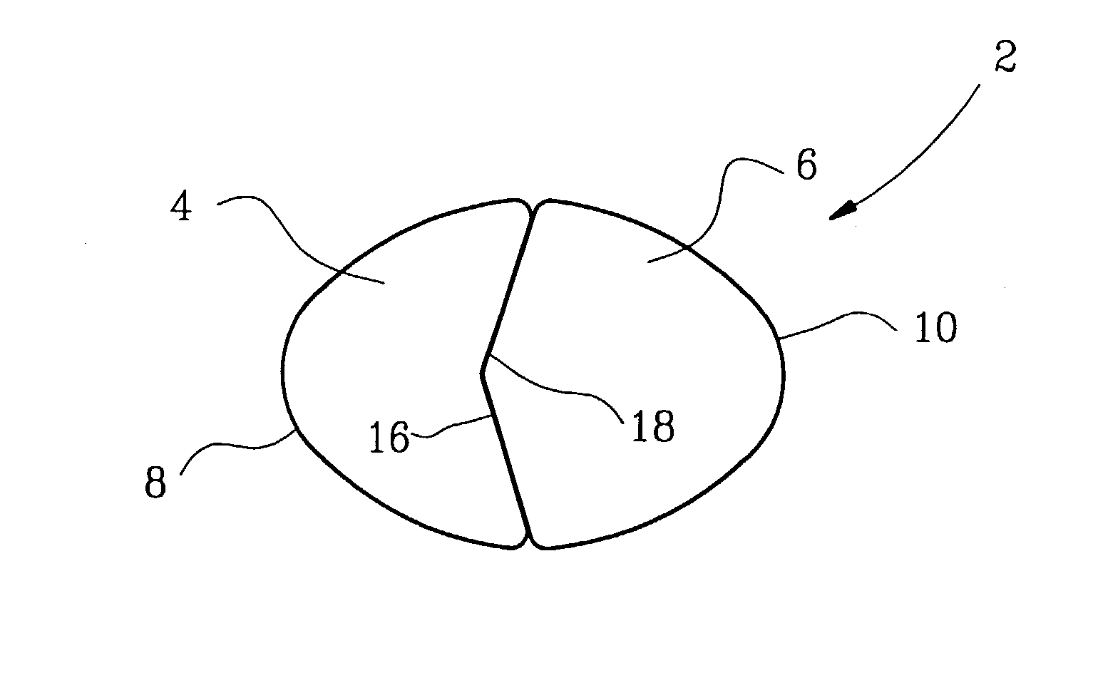
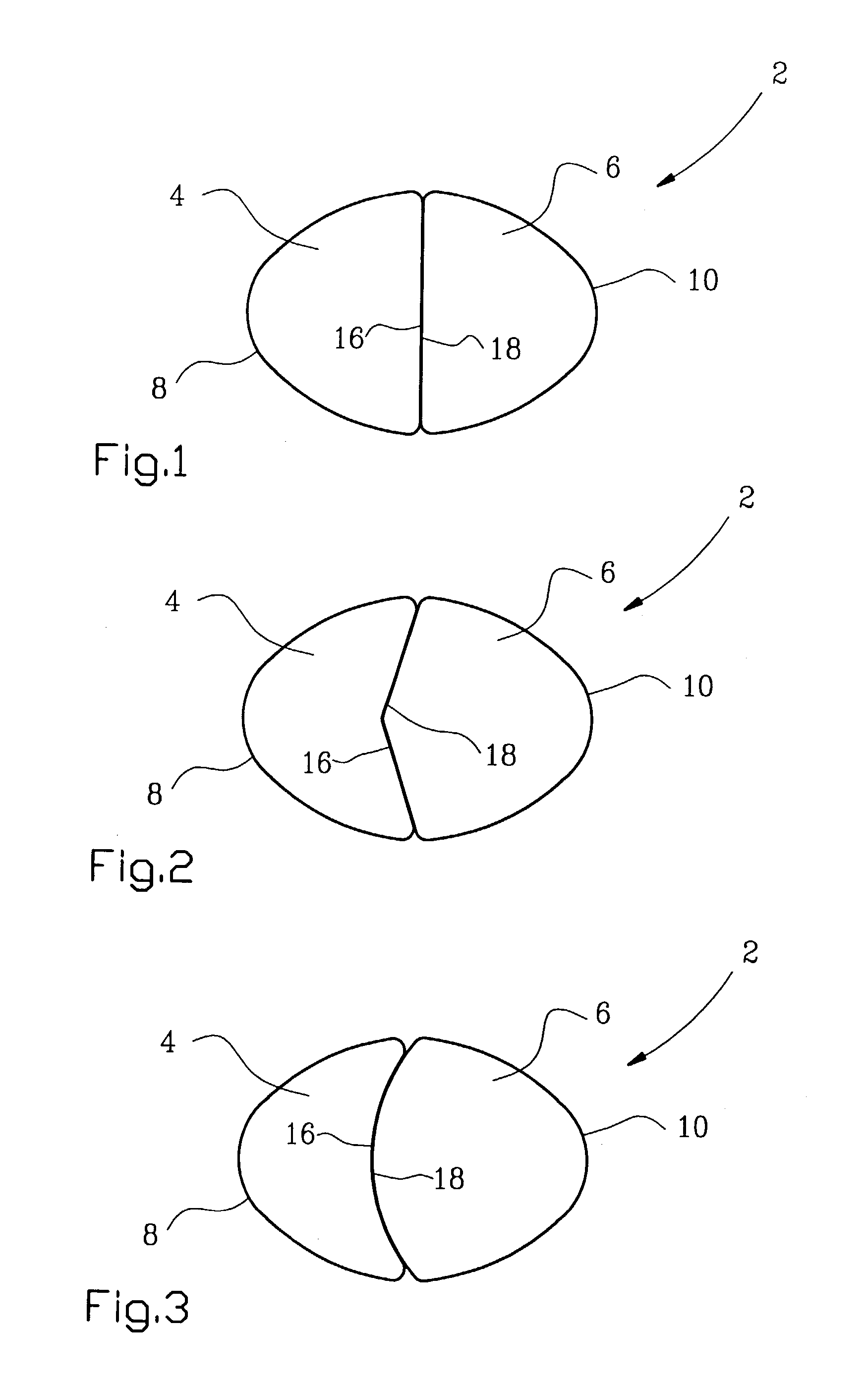
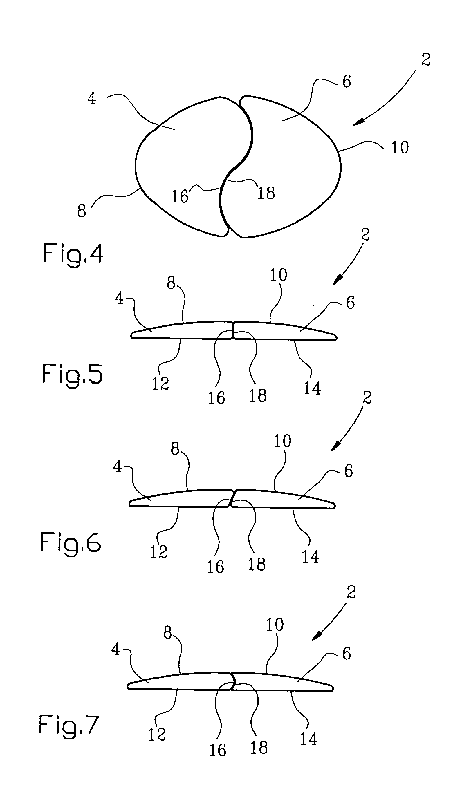
[0041] A pair 2 of retainer elements is formed of a retainer element 4 and a retainer element 6, cooperative in the position of use. Each retainer element 4 and 6 is formed of an outer surface, 8 and 10, respectively, and a basal surface, 12 and 14, respectively, and of a so-called retainer approximal surface 16 and a complementarily shaped retainer approximal surface 18. Correspondingly, a pair of adjacent teeth, a tooth 20 and 22, respectively, is formed of one tooth approximal surface 24 and one adjacent tooth approximal surface 26 and dental attachment surfaces, 28 and 30, respectively, the teeth being anchored in the connective tissues 32 of the tooth jaw. The retainer elements 4 and 6 are positioned and secured / glued to ...


PUM


Abstract

A dental retainer device for stabilization, so-called retention, of pairs of teeth or groups of teeth in a lower jaw and/or an upper jaws in orthodontic treatment. The retainer device is formed of a pair (2) of retainer elements, consisting of two preferably individual, but in the position of use cooperating, retainer elements (4, 6). Each of the retainer elements (4, 6) is formed in with a retainer approximal surface (16, 18), the retainer approximal surfaces (16, 18) being formed complementary relative to one another. In use, one or more pairs (2) of retainer elements is/are positioned and secured with its/their individual elements (4, 6) preferably on the inner face of a tooth (20, 22) each of a pair of adjacent teeth, so that in the position of use the retainer approximal surfaces (16, 18) bear on each other and support, possibly lock, each other. Thereby pairs of teeth or groups of teeth are stabilized while it is possible at the same time to carry out normal dental hygiene by means of a toothbrush, dental floss or toothpicks, which is otherwise difficult to carry out when known retainers are used.

Description

[0001] This invention relates to a dental retention device, also called a dental retainer, for use in patients who have undergone orthodontic treatment, or for some other reason need to have pairs of teeth or groups of teeth retained, or stabilized, in the lower and / or upper jaw(s).[0002] Orthodontic treatment mainly consists of a period of active treatment and a period of inactive treatment. In the period of active treatment the teeth concerned and their connective tissues are moved to the target positions in the jaw(s). The period of active treatment is then followed by a period of inactive treatment, also referred to as the retention period, during which the teeth concerned and their connective tissues are sought to be stabilized, or retained, in the positions obtained. Therefore, in the retention period orthodontic patients must wear suitable retainers 24 hours or part of it a day for up to several years, in order thereby to ensure that the tooth positions obtained are maintaine...

Claims


Application Information

Patent Timeline
IPC IPC(8): A61C7/00A61C7/02A61C7/12
CPCA61C5/007A61C7/02A61C7/006
Inventor AMUNDSEN, OLE CHRISTIAN
Owner AMUNDSEN OLE CHRISTIAN
Why Eureka
Try Eureka