Paintball feed system

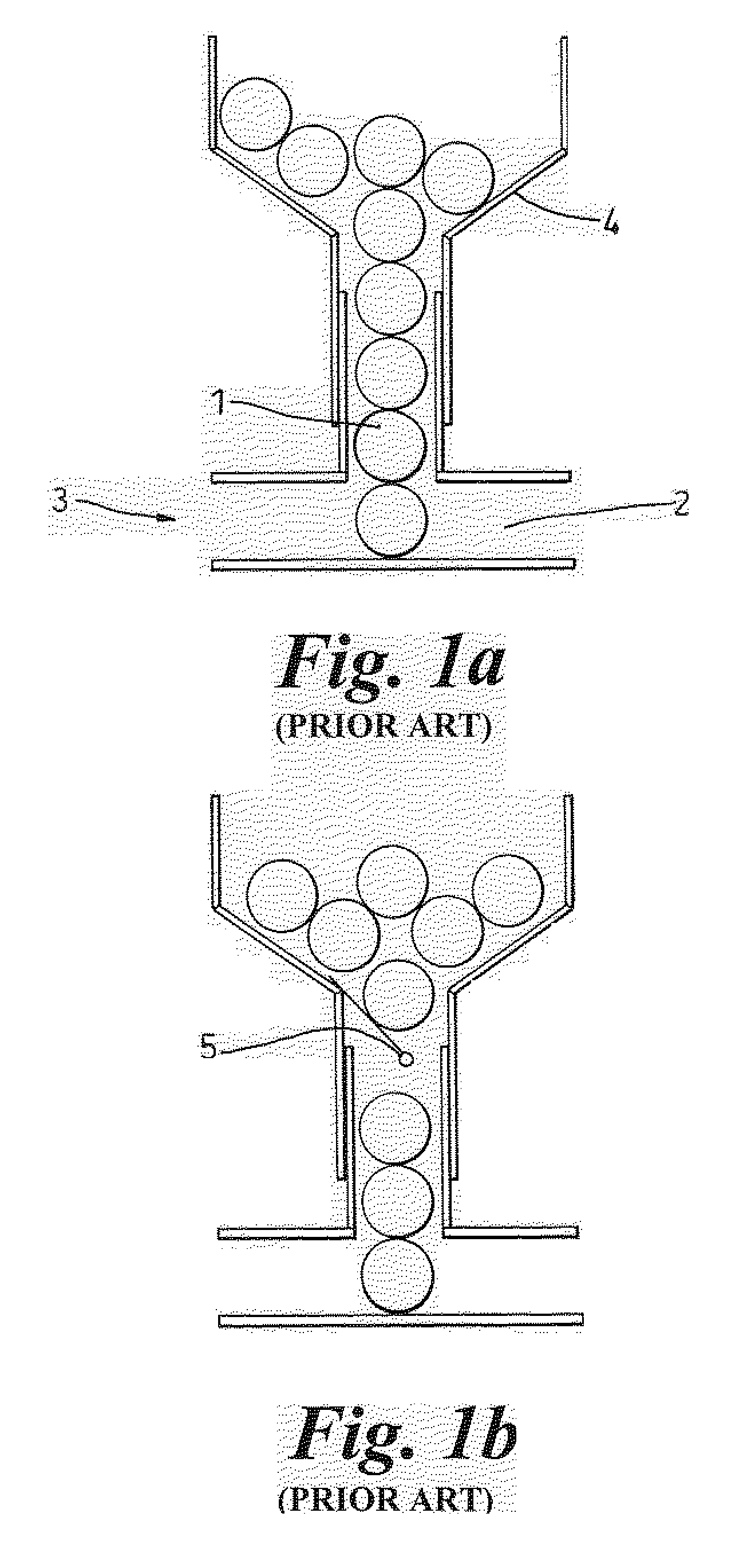
a paintball and feed system technology, applied in the field of paintball feed system, can solve the problems of not being used in the hopper (4), affecting the performance of paintballs, and even affecting the accuracy of paintballs,

Inactive Publication Date: 2003-07-17
NPF
View PDF0 Cites 21 Cited by
  • Summary
  • Abstract
  • Description
  • Claims
  • Application Information

AI Technical Summary

Benefits of technology

[0008] Preferably the detent means is arranged to be spaced from a floor of a breech of the paintball marker and the feed channel is arranged to receive a plurality of paintballs including an uppermost paintball which is in contact with the detent means and a lowermost paintball which is in contact with the floor of the breech whereby vertical movement of the paintballs between the detent means and the floor is inhibited. Preferably the detent means is arranged to allow a paintball to pass in the first direction under its own weight. This helps to ensure that all available paintballs are used up.
[0009] The detent means preferably comprises a plurality of flexible beams, for example three flexible beams, which are spaced around the feed channel. This can help to centre the paintball in the feed channel. The flexible beams preferably extend radially inwards towards the centre of the feed channel, and can conveniently be formed as part of an annular shim from which they project radially inwards.
[0011] The present invention further provides a paintball marker including a paintball feed system, the feed system comprising means defining a feed channel through which paintballs can pass into the marker, flexible detent means arranged to deflect to allow paintballs to pass in a first direction through the channel into the marker, and being further arranged to prevent the passage of the paintballs in a second direction through the channel out of the marker.

Problems solved by technology

This arrangement has the inherent problem that, should the marker (3) be tilted out of a horizontal plane or jolted, the paintball (1) in the breech (2) can pass out of the breech (2) back towards the hopper (4).
Chopped paintballs can foul the marker's firing mechanism leading to impaired performance and even possibly jamming of the marker.
This arrangement does however suffer from the problem that it does not allow a paintball (1) to fall freely under its own weight.
This can result in the last few paintballs (1) in a hopper (4) not being used.
Additionally, due to a lack of rigidity of the strain gauge (5) in the return direction the strain gauge's return prevention is poor.
Thus this arrangement is poor at retaining the paintballs (1) in the breech (2).
Thus existing marker feed systems have the problem that chopping can occur due to the paintballs in a feed tube being able to jiggle in the free space in the feed tube and present a fraction of themselves to the marker's bolt.

Method used


Image

  • Paintball feed system
  • Paintball feed system
  • Paintball feed system

Examples


second embodiment

[0045] In the present invention as shown in Figure 4 and Figure 4a, there is provided a cylindrical collar 38 having an internal circumferential lip 39 at its midpoint. An annular shim 40 having a pair of detent beams 40a, 40b project radially inwardly from it, is held against the lower side of the lip 39, with the beams 40a, 40b extending inwards beyond the lip 39. As shown in Figure 4a, the shim 40 is held in place against the lip 39 by means of a split ring 41 (not shown in Figure 4). The lip 39 and split ring 41 define respectively two sets of support points 42, 44 for the beams 40a, 40b, the one 42 above the beams 40a, 40b being radially further inwards than the one 44 below the beams 40a, 40b. This allows one-way passage of a paintball 46 through the collar 38. The collar 38 is arranged to receive a marker feed tube 48 in one end and a the feeder neck 49 of a hopper 50 in the other end. The collar 38 can be designed such that the beams 40a, 40b reside an integral number of pai...

first embodiment

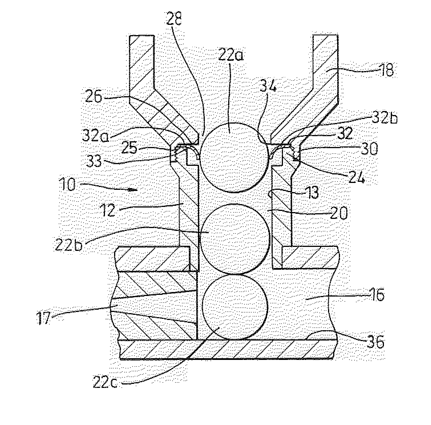
[0050] Referring now to Figure 8, in a modification to the first embodiment described above with reference to Figures 2 to 3d, the detent beams 32a, 32b are each replaced by a detent beam 89. This detent beam 89 has a narrow elongate body 90 and a circular paddle shaped head 92 that is wider than the body 90. The end 95 of the body 90 remote from the head is fixed to the annular part 32 of the shim 31. The increased width of the head 92 in relation to the body 90 results in an increased stiffness of the head 92 compared to the body 90. The first and second support points 33, 34 are aligned with the body 90 and head 92 respectively. Therefore as well as there being a shorter length of the beam 89 extending beyond the second support point 34 than the first support point 33, the part of the beam 90 at the first support point is narrower and hence more flexible than the part 92 are the second support point. Therefore the difference in flexibility of the beam 89 in the upward and downwar...


PUM


Abstract

Abstract of Disclosure A paintball feed system (10) comprises flexible detent beams (32a,b) that flex about first and second support points (33,34) such that they allow a paintball (22a) to pass from a hopper (18) into a feed tube (12) leading to a paintball marker's breech (16) under it's own weight when flexing about the first support point (33). The beams (32a,b) are rigid enough, when flexing about the second support pint (34), to prevent the return of the paintball (22a) back into the hopper (18) from the feed tube (12).

Description

Background of Invention[0001] This invention relates to a paintball feed system. More particularly, but not exclusively it relates to a paintball feed system that is arranged to allow a paintball to pass into a breech of a paintball marker and is arranged to prevent the passage of the paintball out of the breech of the marker.[0002] Referring to Figure 1, it is currently known to feed a paintball (1) into a breech (2) of a paintball marker (3) from a hopper (4) under gravity. This arrangement has the inherent problem that, should the marker (3) be tilted out of a horizontal plane or jolted, the paintball (1) in the breech (2) can pass out of the breech (2) back towards the hopper (4). If the marker is fired while the paintball (1) is not resting on the bottom of the breech (2), "chopping"of the paintball (1) can result whereby the bolt (not shown in Figure 1) splits the paintball (1) because it cannot be propelled along the breech (2). Chopped paintballs can foul the marker's firing...

Claims


Application Information

Patent Timeline
Patent Type & Authority Applications(United States)
IPC IPC(8): F41B11/52
CPCF41B11/52
Inventor RICE , JOHN RONALDMARKS , NICHOLAS JOHNCOLLEY , FRASER
Owner NPF
Why Eureka
Try Eureka