Insertion device for deformable intraocular lens

Inactive Publication Date: 2003-07-24
STAAR JAPAN
View PDF0 Cites 59 Cited by
  • Summary
  • Abstract
  • Description
  • Claims
  • Application Information

AI Technical Summary

Problems solved by technology

Therefore, the necessity of using both hands hinders the ease of use during the operation.
In the conventional insertion device in which the push rod is advanced through an operation of pushing a

Method used


Image

  • Insertion device for deformable intraocular lens
  • Insertion device for deformable intraocular lens
  • Insertion device for deformable intraocular lens

Examples


Embodiment Construction

[0028] An embodiment of the present invention will be described with reference to the accompanying drawings.

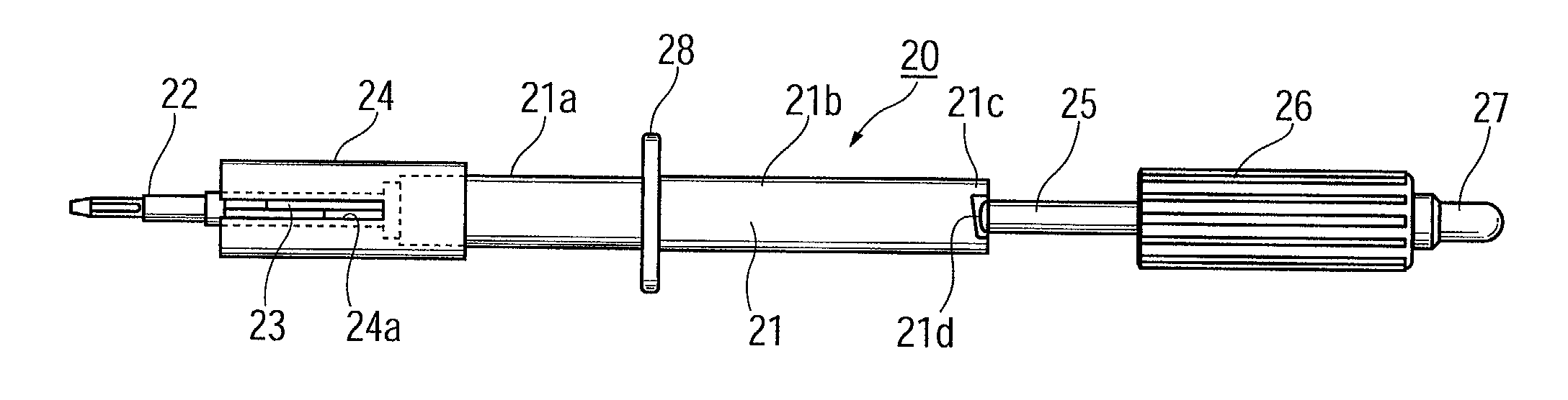
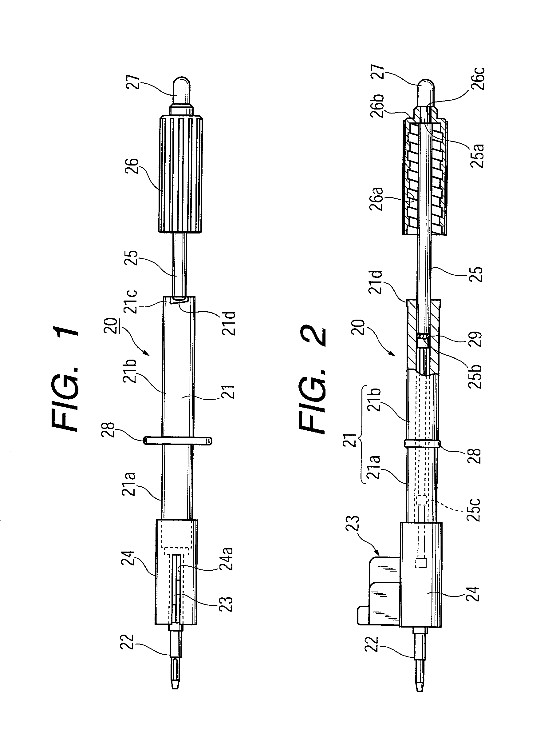
[0029] FIG. 1 is a plan view of an insertion device for a deformable intraocular lens according to an embodiment of the present invention; and FIG. 2 is a partially cutaway side view of the insertion device.

[0030] In these drawings, reference numeral 20 denotes an insertion device which includes a device body 21 having a smaller diameter portion 21a at the front end side and a larger diameter portion 21b at the rear end side. An insertion tube 22 is fixed to the front end of the device body 21 in such a manner that an axially extending inner cavity of the insertion tube 22 is aligned with an axially extending inner cavity of the device body 21. An enclosing member 23 is provided on the insertion tube 22. The enclosing member 23 has a lens receiving section and an open / close mechanism and adapted to reduce the exterior size of a deformable intraocular lens. A cylindrical slide ...


PUM


Abstract

An insertion device can deform a deformable intraocular lens into a smaller size and insert the intraocular lens into the eye. The insertion device includes a device body; an insertion tube attached to a front end of the device body and adapted to be inserted into the eye; and a push rod axially movable within the device body and the insertion tube and adapted to insert the intraocular lens into the eye when advanced. A drive member is rotatably provided at a rear end of the push rod. A motion conversion mechanism is disposed between the device body and the drive member and is adapted to axially move the drive member, upon rotation of the drive member, in order to axially move the push rod. A push member is provided at the rear end of the push rod and projects rearward from the drive member.

Description

[0001] 1. Field of the Invention[0002] The present invention relates to an insertion device for inserting a deformable intraocular lens into the eye. Examples of such a deformable intraocular lens include a deformable intraocular lens that is inserted into the eye in place of the natural lens when the latter is physically extracted because of cataracts, and a vision correction lens that is inserted into the eye for the sole purpose of vision correction.[0003] 2. Description of the Related Art[0004] Implantation of an intraocular lens for treating cataract has been widely performed since 1949, when Ridley implanted for the first time an artificial lens; i.e., an intraocular lens, into the human eye in place of an opaqued natural lens during cataract surgery.[0005] As disclosed in Japanese Patent Application Laid-Open (kokai) No. 58-146346, there have been invented improved intraocular lenses which can be inserted into the eye through a small incision formed in the eyeball. In one of ...

Claims


Application Information

Patent Timeline
IPC IPC(8): A61F9/007A61F2/16
CPCA61F2/167
Inventor KIKUCHI, TOSHIKAZUKOBAYASHI, KENICHI
Owner STAAR JAPAN
Why Eureka
Try Eureka