Method and apparatus for shielding wire for MRI resistant electrode systems

a shielding wire and electrode technology, applied in the field of shielding wire for mri resistant electrode systems, can solve the problems of damage to the device, complex tasks, and vastly more complex implantable medical devices than their predecessors, and achieve the effects of reducing the effect, and reducing the cost of medical equipmen

Inactive Publication Date: 2003-07-31
MEDTRONIC INC
View PDF2 Cites 205 Cited by
  • Summary
  • Abstract
  • Description
  • Claims
  • Application Information

AI Technical Summary

Problems solved by technology

Today's implantable medical devices are also vastly more sophisticated and complex than their predecessors, and are therefore capable of performing considerably more complex tasks for reducing the effects of these health ailments.
Problems may be associated with implanted leads when a patient comes in contact with alternating electromagnetic fields.
If this current is large, damage to the device can occur.
Additionally, the implanted medical device can sense the imposed voltage on the lead and react inappropriately, resulting in the wrong therapy being administered.
These techniques can give valuable diagnostic information without the need for invasive surgery, but also subject the patient to significant alternating electromagnetic fields, resulting in the risks described above.
As noted above, the large currents induced by electromagnetic fields can result in damage to, or improper operation within, device circuitry.
These induced currents can also result in injury to the patient.
Because the tissue area associated with electrode contact may be very small, the current densities may be high, resulting in heating that can injure the tissue.
Moreover, a sudden burst of radio-frequency energy can cause an electric pulse within the lead that could send the heart into fibrillation.
For both of these reasons, this type of high-density current may be fatal.

Method used


Image

  • Method and apparatus for shielding wire for MRI resistant electrode systems
  • Method and apparatus for shielding wire for MRI resistant electrode systems
  • Method and apparatus for shielding wire for MRI resistant electrode systems

Examples


Embodiment Construction

[0028] Illustrative embodiments of the invention are described below. In the interest of clarity, not all features of an actual implementation are described in this specification. It will of course be appreciated that in the development of any such actual embodiment, numerous implementation-specific decisions must be made to achieve the developers' specific goals, such as compliance with system-related and business-related constraints, which will vary from one implementation to another. Moreover, it will be appreciated that such a development effort might be complex and time-consuming, but would nevertheless be a routine undertaking for those of ordinary skill in the art having the benefit of this disclosure.

[0029] Embodiments of the present invention provide for means to reduce the potentially harmful effects that can occur when a medical implantable device is subjected to electromagnetic energy fields.

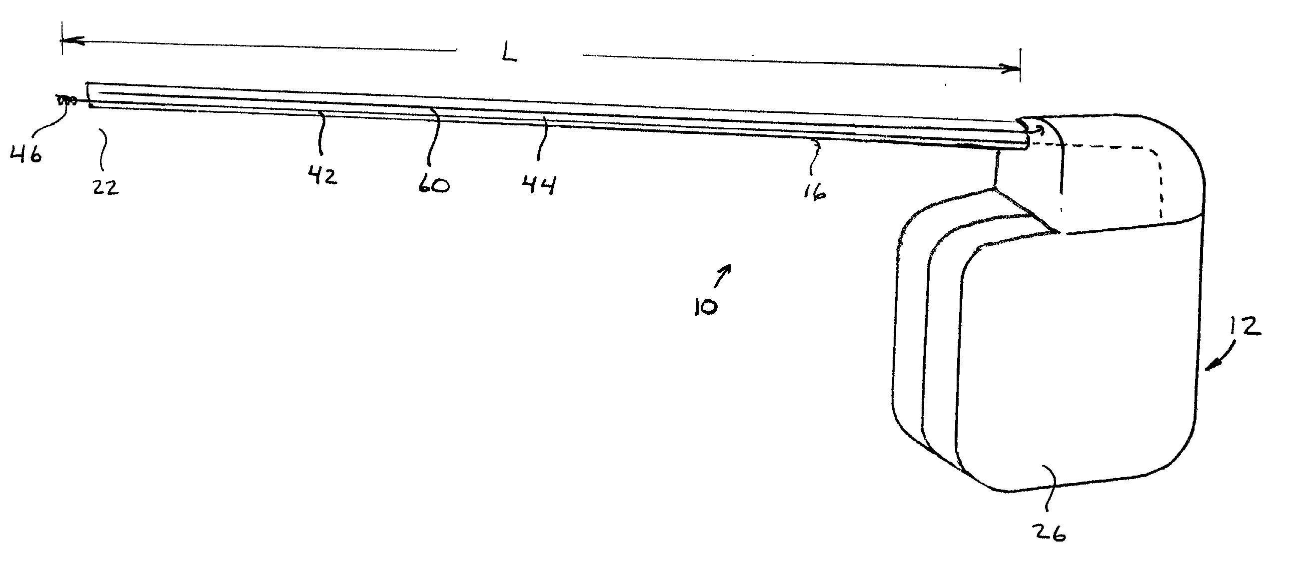
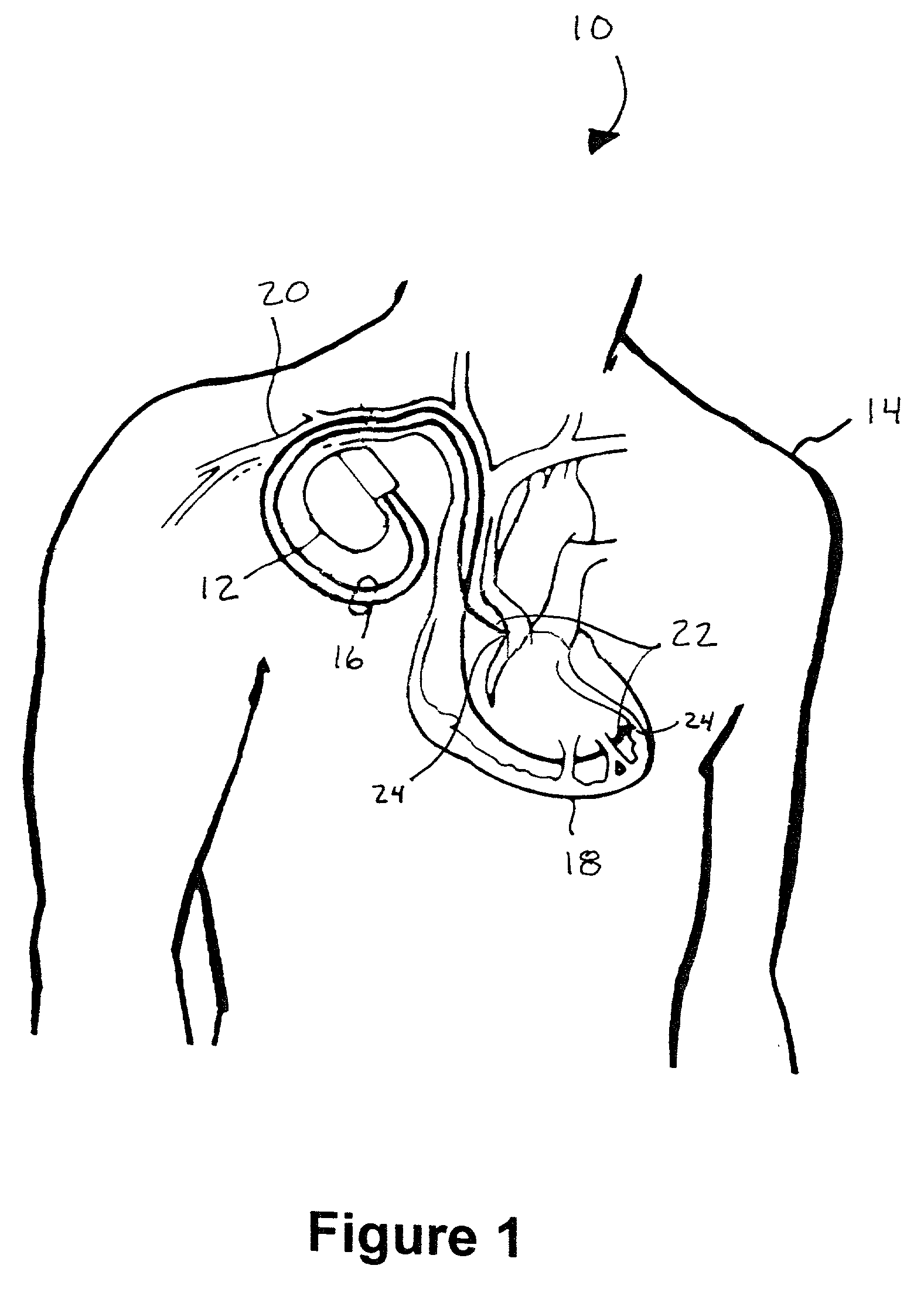
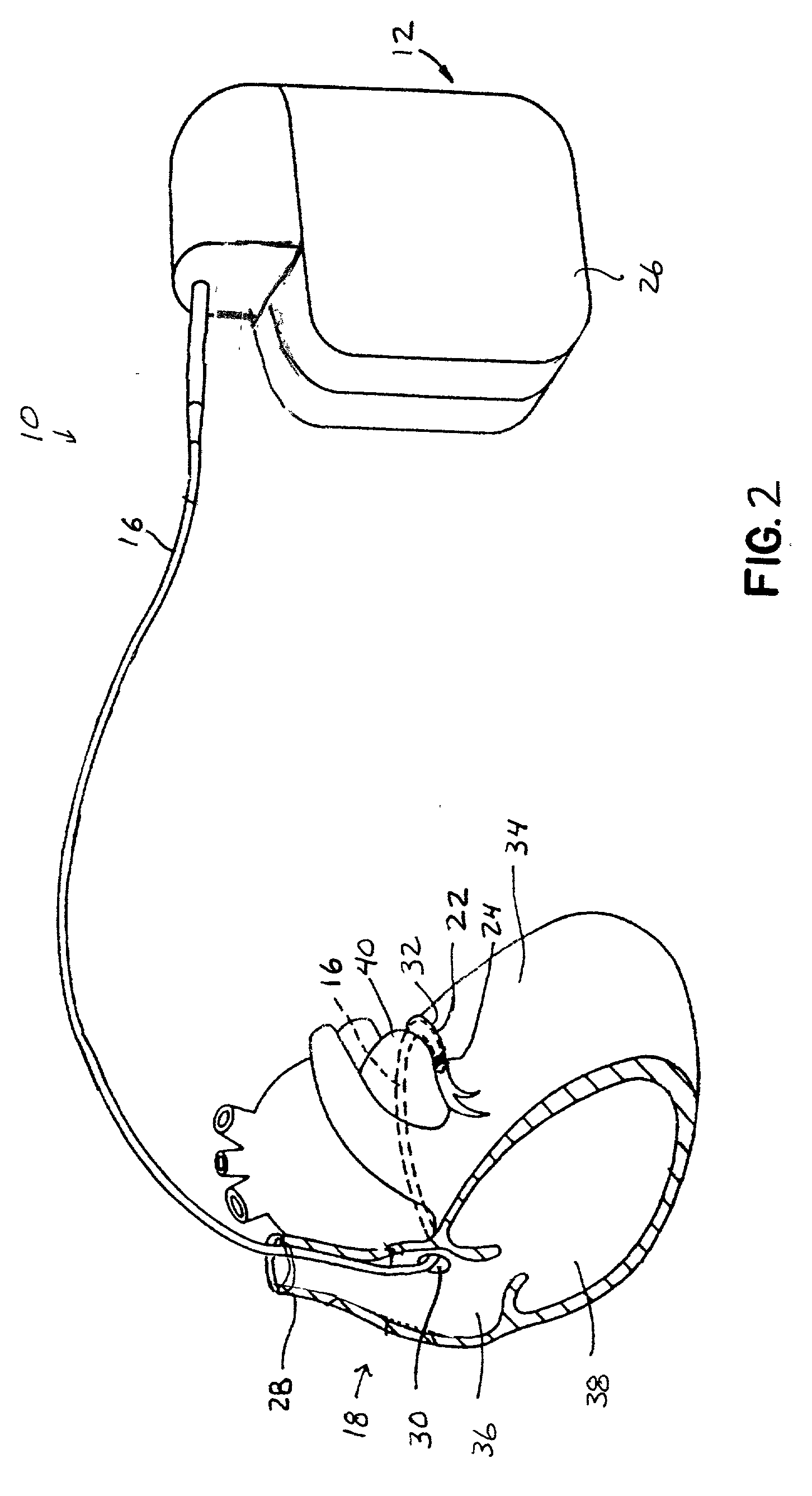
[0030] FIG. 1 illustrates an implantable medical device (IMD) system 10, which i...


PUM


Abstract

The present invention discloses apparatus and methods for use with implantable medical system. In one embodiment a medical electrical lead is disclosed comprising an electrode wire and a shield wire adjacent to at least a portion of the electrode wire, the electrical lead is capable of insertion within a body and the shield wire is electrically separated from the electrode wire. In another embodiment of the invention a method of shielding a medical electrical lead is disclosed. The method comprises receiving electromagnetic energy within a shield wire that is adjacent at least a portion of the lead. The energy is dissipated into a living body, thus reducing the amount of electromagnetic energy received by the medical electrical lead.

Description

[0001] This invention relates generally to a method and apparatus for electrically stimulating a heart, and, more particularly, to a method and apparatus for reducing the effects of an electromagnetic field on the operation and safety of implantable medical devices.DESCRIPTION OF THE RELATED ART[0002] Since their earliest inception some forty years ago, there has been a significant advancement in body-implantable electronic medical devices. Today, these implantable devices include therapeutic and diagnostic devices, such as pacemakers, cardioverters, defibrillators, neural stimulators, drug administering devices, among others for alleviating the adverse effects of various health ailments. Today's implantable medical devices are also vastly more sophisticated and complex than their predecessors, and are therefore capable of performing considerably more complex tasks for reducing the effects of these health ailments.[0003] A variety of different implantable medical devices (IMD) are a...

Claims


Application Information

Patent Timeline
Patent Type & Authority Applications(United States)
IPC IPC(8): A61N1/05A61N1/08
CPCA61N1/05A61N2001/086A61N1/086
Inventor ZEIJLEMAKER, VOLKERT A.
Owner MEDTRONIC INC
Why Eureka
Try Eureka