Apparatus and methods for providing a flight display in an aircraft

a technology for aircraft and display devices, applied in the field of aircraft display devices and methods, can solve the problems of limited functionality, scope, utility, and confusion of pilots, and the lack of uniform arrangement of flight instruments

Inactive Publication Date: 2003-09-25
TOYOTA MOTOR SALES USA
View PDF39 Cites 44 Cited by
  • Summary
  • Abstract
  • Description
  • Claims
  • Application Information

AI Technical Summary

Problems solved by technology

The lack of uniformity in the arrangement of these flight instruments can be confusing to a pilot, particularly if the pilot flies more than

Method used


Image

  • Apparatus and methods for providing a flight display in an aircraft
  • Apparatus and methods for providing a flight display in an aircraft
  • Apparatus and methods for providing a flight display in an aircraft

Examples


Embodiment Construction

[0044] A. Introduction

[0045] The present invention relates to apparatus and methods for providing flight instruments on a flight display in an aircraft. In the following paragraphs, several examples of apparatus and methods for providing flight instruments on a flight display in an aircraft are provided. However, these examples are exemplary, and other apparatus and methods may be used for providing flight instruments on a flight display.

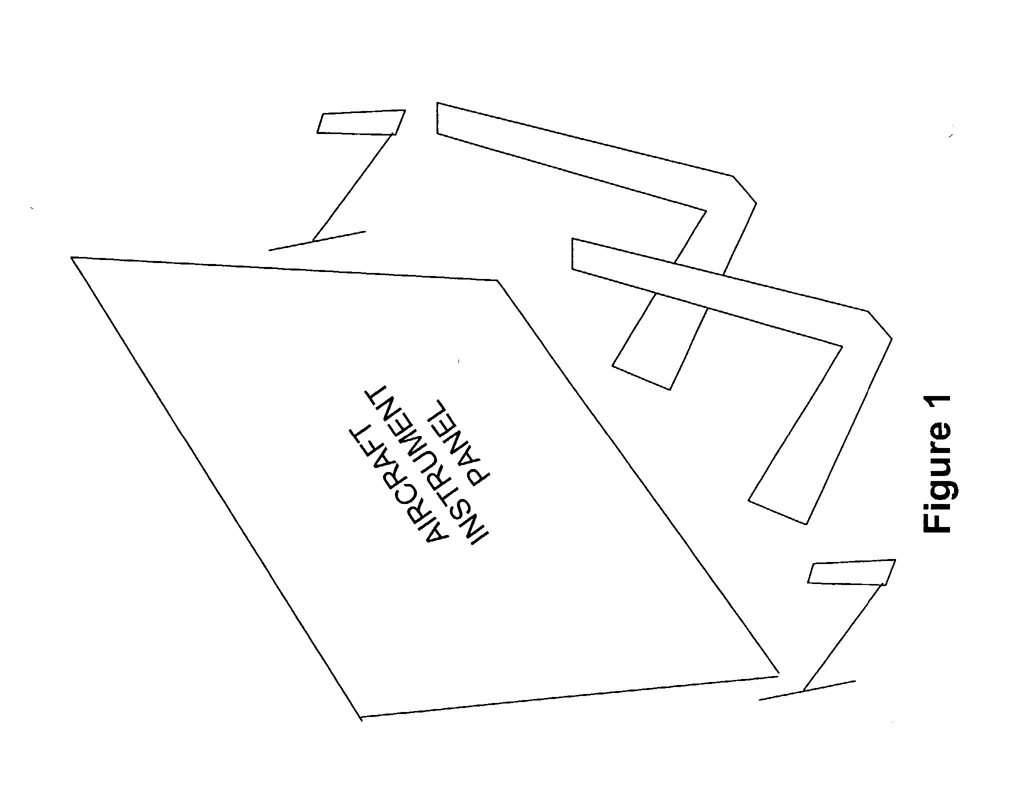
[0046] FIG. 1 is a representation of a cockpit in an aircraft. As shown in FIG. 1, a cockpit 100 includes a pilot seat 120, a co-pilot seat 140, control mechanisms 160, and an aircraft instrument panel 180. The cockpit may also contain other components (not shown).

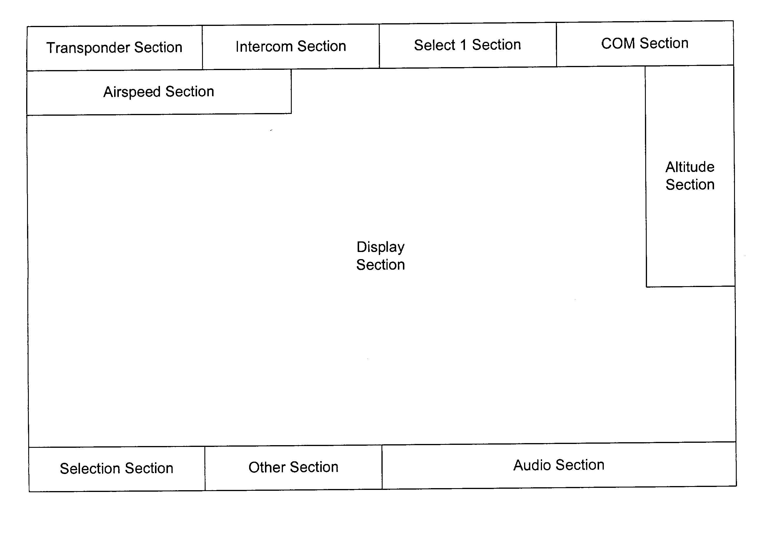
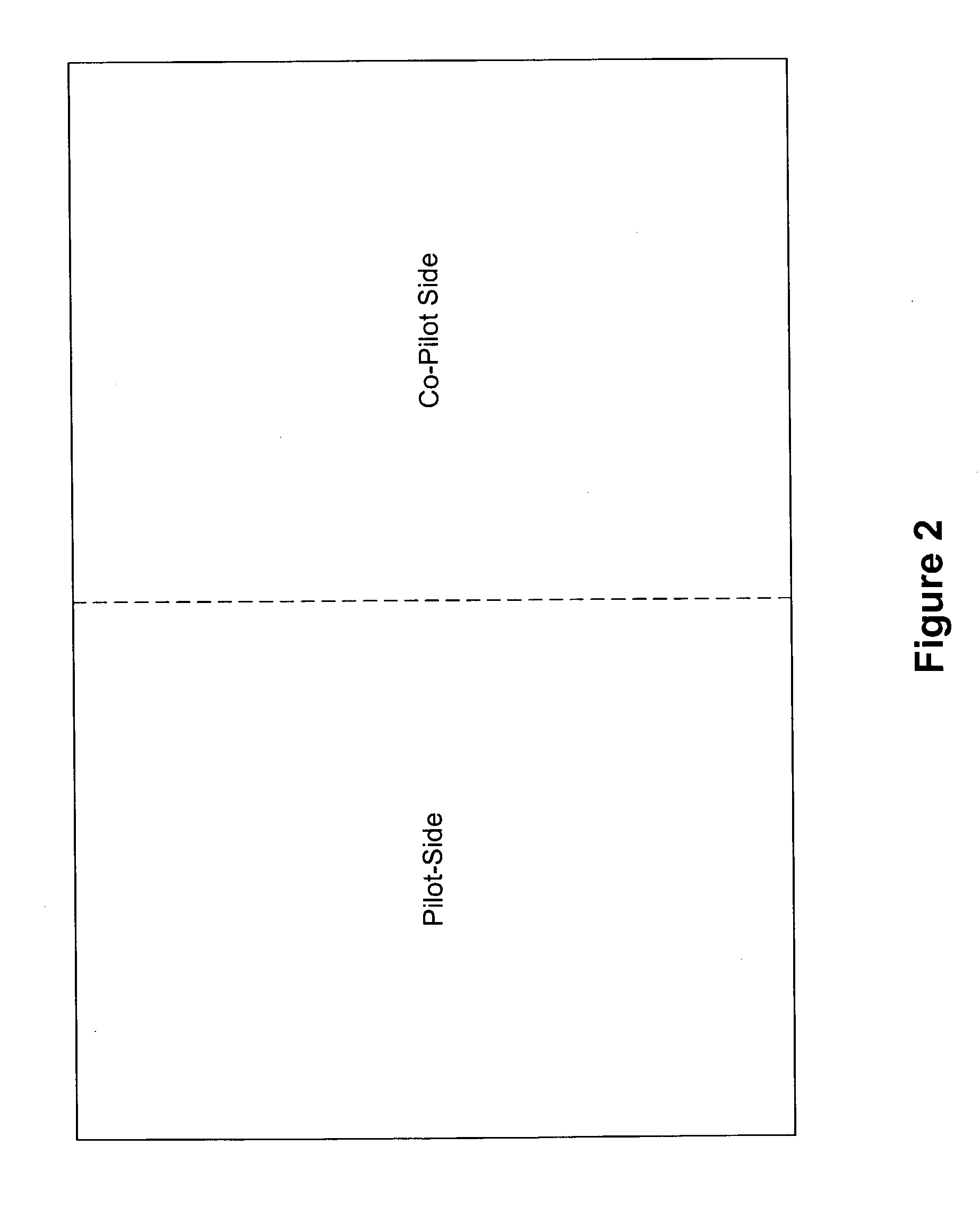
[0047] FIG. 2 is a general diagram of an aircraft instrument panel, as shown in FIG. 1. As shown in FIG. 2, an aircraft instrument panel 200 includes a pilot side 220 and a co-pilot side 240. In one implementation, pilot side 220 may be equally proportioned to co-pilot side 240. In other i...


PUM


Abstract

Apparatus and methods are provided for flight instruments in an electronic format. The flight instruments may appear in a standard configuration, including both primary flight instruments and secondary flight instruments. The apparatus and methods may also provide some or all of the primary flight instruments in one visual representation.

Description

I. RELATED APPLICATION[0001] This application claims the benefit of U.S. Provisional Patent Application No. 60 / 350,430 for Apparatus and Methods for Providing a Flight Display in an Aircraft, which is expressly incorporated herein by reference. Application No. 60 / 350,430 was filed on Jan. 24, 2002, by Bassam H. Chamas, Joseph S. Nalbach and Ryuichi Yokota.II. TECHNICAL FIELD[0002] The present invention relates to apparatus and methods for providing a flight display in an aircraft. In particular, the present invention relates to apparatus and methods for providing flight instruments on a flight display in an aircraft.III. BACKGROUND[0003] Currently, the flight instruments in many aircraft are based on mechanical devices. In most aircraft, these mechanical devices include various types of instruments, including vacuum-driven instruments, pitot-static-driven instruments, and electrical-driven instruments. Although providing safety through redundancy, most of the primary flight instrume...

Claims


Application Information

Patent Timeline
IPC IPC(8): G01C23/00
CPCG01C23/005
Inventor CHAMAS, BASSAM H.NALBACH, JOSEPH S.YOKOTA, RYUICHI
Owner TOYOTA MOTOR SALES USA
Why Eureka
Try Eureka