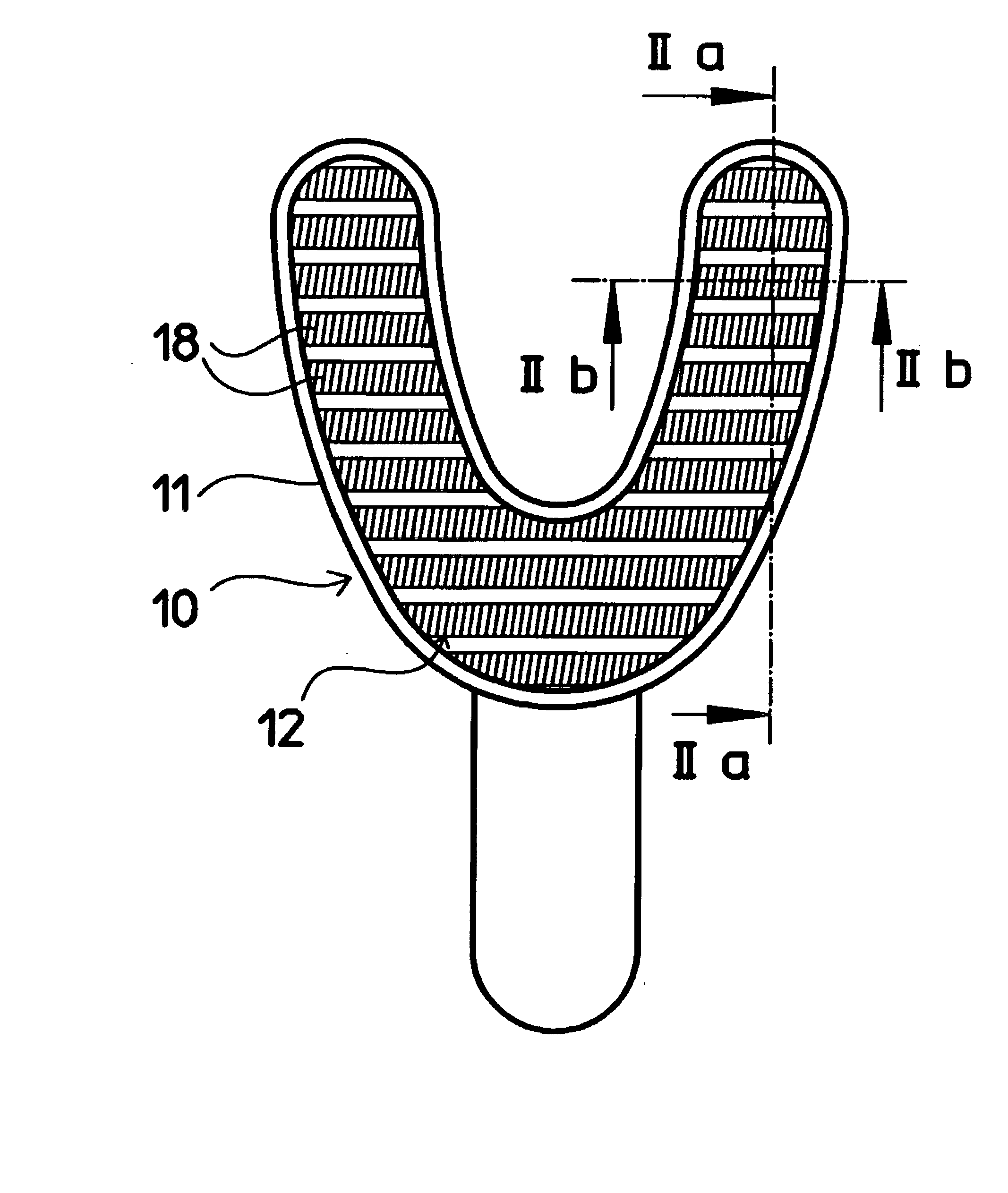
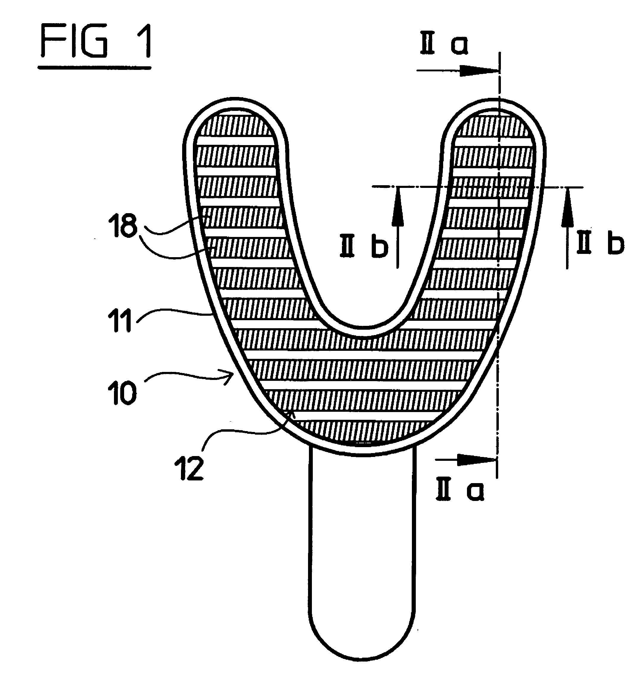
Dental impression tray with impression material retainer

a technology of impression material and retainer, which is applied in the field of dental impression trays, can solve the problems of limited penetration of impression, easy torn out of hardened impression material, and impression material having a relatively high viscosity,

Inactive Publication Date: 2003-09-25
3M DEUTLAND +1
View PDF18 Cites 9 Cited by
  • Summary
  • Abstract
  • Description
  • Claims
  • Application Information

AI Technical Summary

Problems solved by technology

One disadvantage of this known impression tray is that an impression material having a relatively high viscosity may penetrate only slightly into the felt mat.
For this reason, only a few filaments located on the top of the felt mat may become embedded in the impression material and, as a consequence, may be easily torn out of the hardened impression material when the impression tray is removed from the jaw, because of the high tensile forces that occur during this procedure.
The impression material may push down and compress even a thick felt mat so there will be only a limited penetration of the impression material around the filaments of a thick mat.
There is a risk of the impression material detaching from the impression tray and losing its original shape, as a result of which the subsequent dental work loses out on accuracy of fit.
This air space creates a defect in the impression and stone model in some cases.
A defect is created whether the tooth contacts the loop material or the inner surface of the tray.
This situation also causes a defect in the impression and thus the stone model.
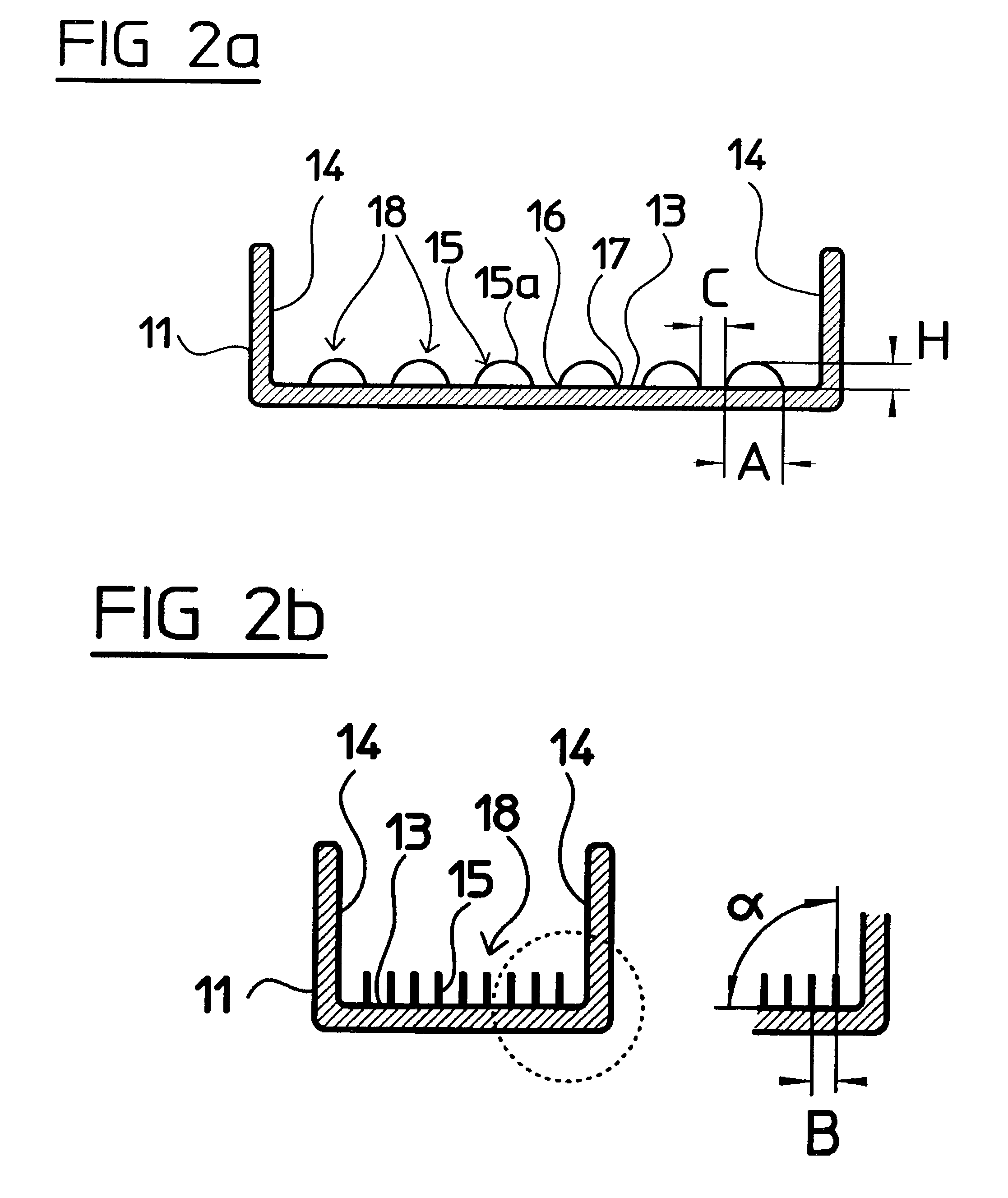
However, other arrangements in which the distances B and C are not uniform or in which the rows are not parallel are also possible.
However, these representations are not exhaustive and many other side elevation shapes are also possible.
However, these representations are not exhaustive and other cross-sectional profiles are also possible.

Method used


Image

  • Dental impression tray with impression material retainer
  • Dental impression tray with impression material retainer
  • Dental impression tray with impression material retainer

Examples


Embodiment Construction

[0110] Retention Capacity Test

[0111] In this example the retention capacity of a dental impression tray according to the invention was evaluated by measuring in a first test cycle the tensile strength (tensile force) of the bond formed between an impression material and a known dental adhesive typically used to bond an impression material to a simple tray, by measuring in a second test cycle the tensile strength of the bond formed between the same impression material and a dental tray according to the invention, and by then comparing the results of the two test cycles. The tensile strength of the bond formed between the dental impression material and the retainer is a measure of the retention capacity of a dental tray according to the invention as determined according to the Retention Capacity Test described herein.

[0112] More specifically, a universal tensile test machine "UPM 1435" from ZWICK out-fitted with a 5 kN force sensor, and a pair of 27 mm diameter brass test plates was p...


PUM


Abstract

A dental impression tray comprises a trough for receiving dental impression material and at least one retainer on at least a portion of an inner surface of the trough. The retainer comprises a plurality of anchoring elements, each of which comprises a first end, a second end, and an arc between the first and second ends. The first and second ends of the anchoring elements are connected to the inner surface of the trough, and the arcs project from the inner surface of the trough. The loop material of a hook and loop mechanical fastener is a particularly useful retainer.

Description

[0001] This patent application is a continuation-in-part of U.S. patent application Ser. No. 10 / 105,199, filed on Mar. 25, 2002, which application is hereby incorporated by reference in its entirety.[0002] 1. Technical Field[0003] The present invention relates generally to dental impression trays and, more specifically, to dental impression trays having a dental impression material retainer incorporated therein.[0004] 2. Description of the Related Art[0005] EP 0 096 020 B 1 discloses a dental impression tray comprising a trough for receiving dental impression material and a porous felt anchoring mat. The trough is provided on at least certain portions of its inside surface with the felt mat. The felt mat serves to hold the hardened impression material in the impression tray when the impression tray is removed from the jaw. The felt mat is made up of filaments which are distributed uniformly in all directions and which lie close to each other on the inside of the trough and are attac...

Claims


Application Information

Patent Timeline
Patent Type & Authority Applications(United States)
IPC IPC(8): A61C9/00
CPCA61C9/0006
Inventor BURGIO, PAUL A.WAGNER, INGO W.
Owner 3M DEUTLAND
Why Eureka
Try Eureka