Automatically tracking scanning sonar

a scanning sonar and automatic tracking technology, applied in the field of scanning sonar, can solve the problem that scanning sonar cannot continue the ordinary automatic tracking operation, and achieve the effect of avoiding undesired bottom echo tracking

Inactive Publication Date: 2003-10-30
FURUNO ELECTRIC CO LTD
View PDF4 Cites 37 Cited by
  • Summary
  • Abstract
  • Description
  • Claims
  • Application Information

AI Technical Summary

Benefits of technology

0010] It is a second object of the invention to provide a scanning sonar which can automatically track bottom fish existing close to the bottom by distinctly separating a fish echo from a bottom echo, thereby avoiding undesired tracking of the bottom echo.

Problems solved by technology

In a situation where the echo of the target is not received due to aeration or when the target has moved to just beneath own ship on which the scanning sonar is installed, the scanning sonar will not be able to continue the ordinary automatic tracking operation.

Method used


Image

  • Automatically tracking scanning sonar
  • Automatically tracking scanning sonar
  • Automatically tracking scanning sonar

Examples


Embodiment Construction

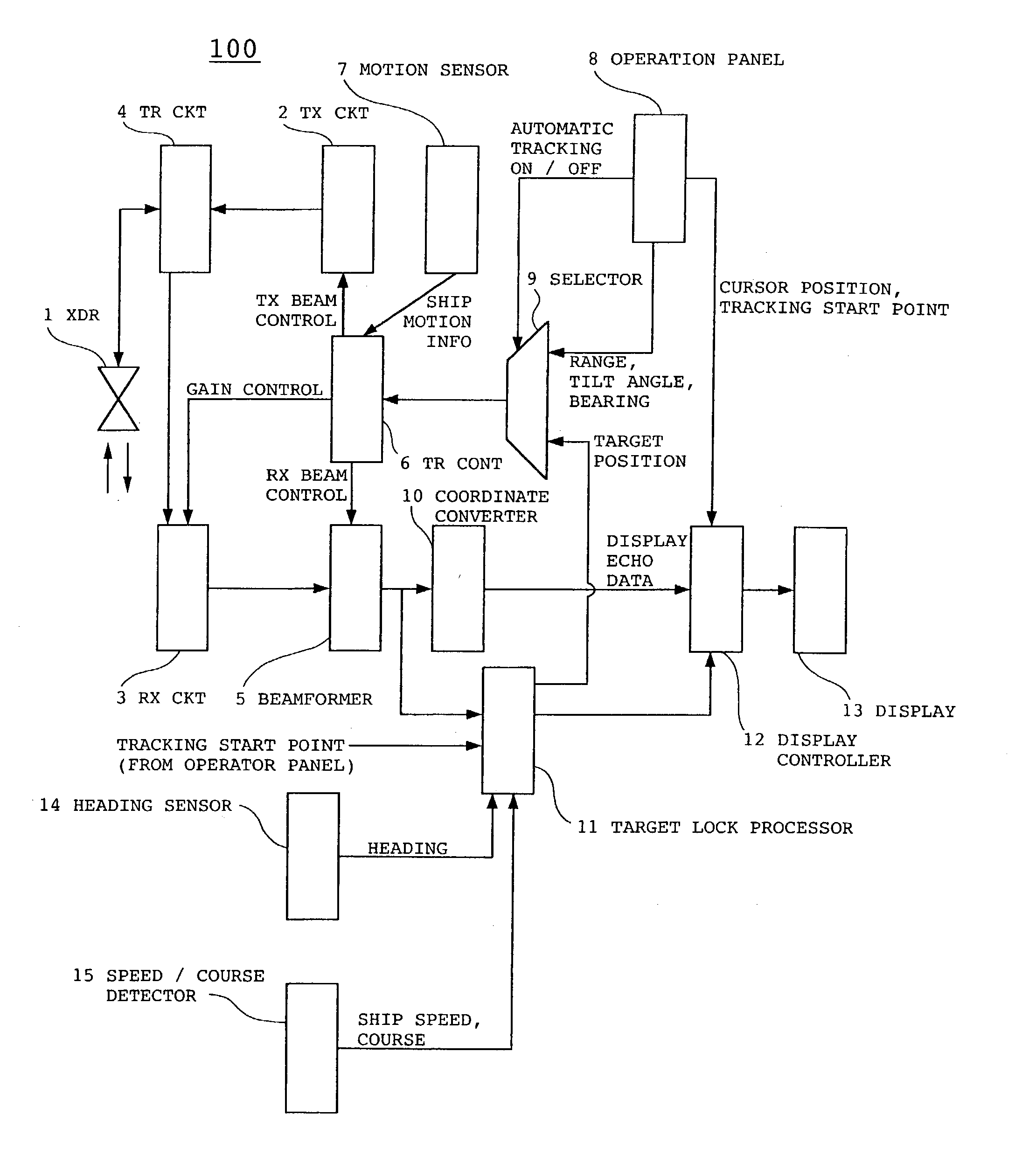
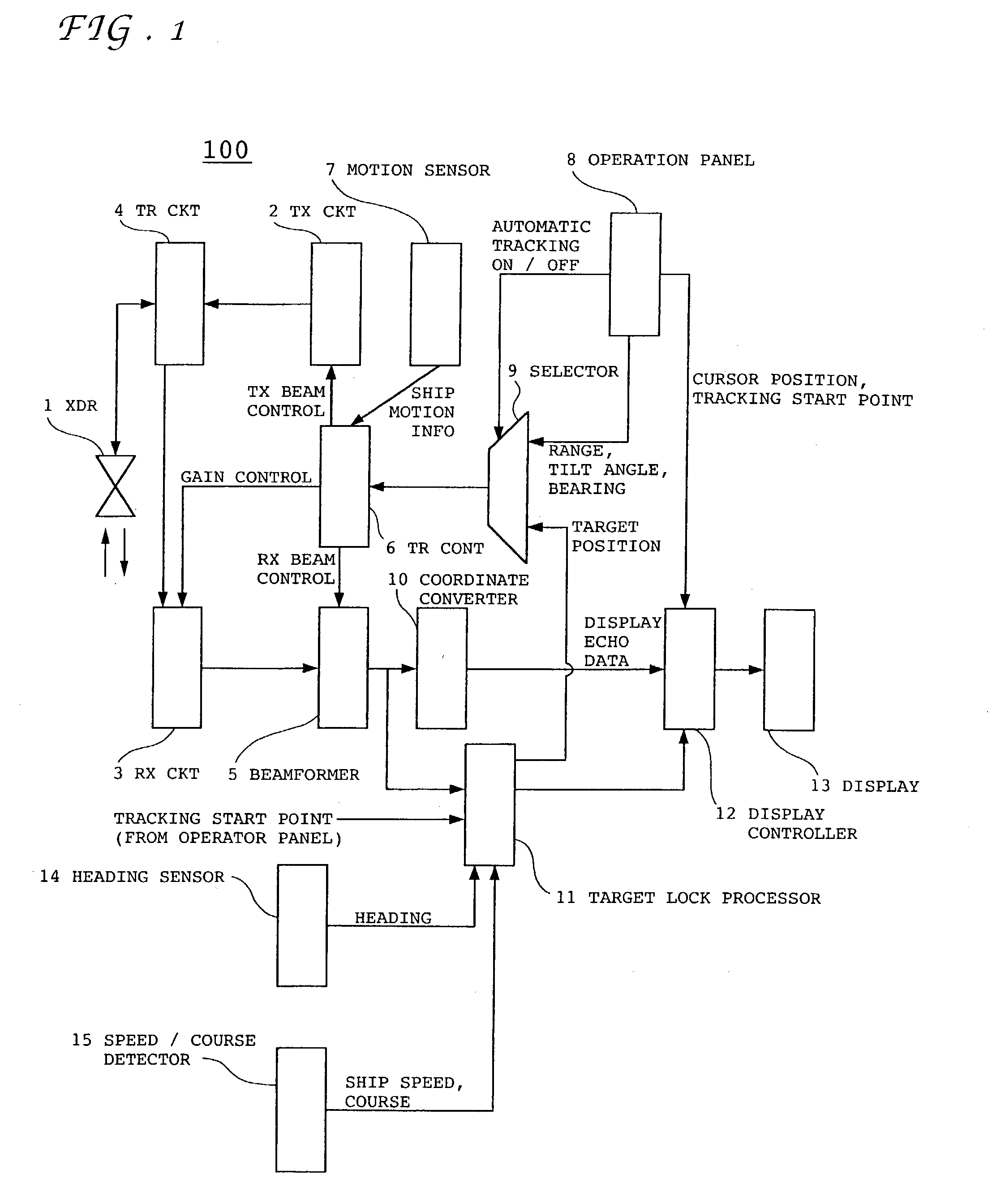
[0037] FIG. 1 is a block diagram of an automatically tracking scanning sonar 100 according to a preferred embodiment of the invention, in which designated by the numeral 1 is a transducer which emits a ping of ultrasonic waves underwater every transmission cycle by converting an electric transmitting signal, receives echo signals returning from underwater targets and coverts the received echo signals into an electric signal every receiving cycle. The transducer 1 includes a number of transducer elements arranged in a cylindrical shape, although the transducer 1 may be of other shapes, such as a sphere. Designated by the numeral 2 is a transmitter circuit which outputs a transmitting signal for emitting an ultrasonic transmitting beam 53 in all directions around the transducer 1, forming an umbrellalike beam pattern directed obliquely downward with a specific tilt angle .delta. as shown in FIG. 12, in horizontal scanning mode. In vertical scanning mode, on the other hand, the transmi...


PUM


Abstract

An automatically tracking scanning sonar alternately performs horizontal scanning and vertical scanning and a target lock processor calculates a predicted position of a target based on an echo signal previously received from the target when the echo signal from the target is interrupted. A selector sets a range, tilt angle and sounding direction and outputs them to a transmit-receive controller such that the scanning sonar can scan the predicted target position. As the depth of the target is determined by performing the vertical scanning, the tilt angle of an umbrellalike beam pattern produced by the horizontal scanning can be varied to follow the target by controlling the tilt angle based on target depth information even when the target moves in vertical directions. It is therefore possible to automatically track the target in a reliable fashion.

Description

[0001] 1. Field of the Invention[0002] This invention relates to a scanning sonar designed to automatically track underwater targets, such as fish.[0003] 2. Description of the Prior Art[0004] A scanning sonar is an underwater sounding apparatus which typically emits an ultrasonic sounding beam in all directions underwater with a specific tilt angle from water surface, receives echo signals returning from underwater targets all around and displays target images based on the echo signals. FIG. 12 is a diagram showing a general principle of the scanning sonar. Referring to FIG. 12, designated by the numeral 50 is a scanning sonar installed on a ship 51, designated by the numeral 52 is a transducer of the scanning sonar 50, designated by the numeral 53 is an ultrasonic transmitting beam emitted from the transducer 52, and designated by the numeral 54 is water surface. The ultrasonic transmitting beam 53 is transmitted underwater simultaneously in all directions around the transducer 52,...

Claims


Application Information

Patent Timeline
Patent Type & Authority Applications(United States)
IPC IPC(8): G01S15/66G01S15/42G01S15/89G01S15/96
CPCG01S15/42G01S15/96G01S15/89G01S15/66
Inventor ISHIHARA, SHINJIITO, YASUOYAMASHINA, NOBUHARU
Owner FURUNO ELECTRIC CO LTD
Why Eureka
Try Eureka