PWM rendering for color/gray-scale text and graphics for laser printer

a laser printer and color/grayscale technology, applied in the direction of digital output to print units, visual presentation using printers, instruments, etc., can solve the problems of high frequency, high distortion, and high frequency of sharp edges and corners, and achieve enhanced edge rendition, precise placement of subpixels, and improved edge rendition in toner-transfer printers

Inactive Publication Date: 2003-11-13
SEIKO EPSON CORP
View PDF12 Cites 44 Cited by
  • Summary
  • Abstract
  • Description
  • Claims
  • Application Information

AI Technical Summary

Benefits of technology

[0015] It is an object of the present invention to provide a technique for achieving improved edge rendition in toner-transfer printers. The invention provides enhanced edge rendition through precise placement of subpixels within pixel cells that are located on or near edges in an image. Image data is examined to identify a "target pixel" near the edge of an object that represents the object and is adjacent to a "background pixel" that represents only background. A "second pixel", adjacent to the target pixel and representing the object, is also identified. The invention analyzes the target pixel's location with respect to the second pixel to determine the placement of a subpixel within the target pixel cell and the placement of a subpixel within the second pixel cell such that the edge of the object is well-defined and the density of the object is preserved. A vertical smoothing process can additionally be performed to improve further the appearance of edges in the image. This technique is particularly advantageous for printing a halftoned object represented by pixels that are not saturated.

Problems solved by technology

Straight lines, sharp edges and corners and other high contrast features contain very high frequencies and often cannot be rendered accurately.
If a high-frequency feature such as a sharp edge is rendered with a pixel resolution that is insufficient to capture all of the visible information contained within the image, artifacts will appear.
Certain visual artifacts are particularly problematic: diagonal lines and boundaries between different regions tend to have a jagged step or staircase appearance that is often quite visible.
The appearance of jagged edges and other artifacts in digitized images is a significant problem that is encountered when using a toner-transfer printing device for printing.
Although printing devices can selectively use continuous tone or halftone formats to generate each pixel on the print medium, current printing devices require a trade-off between the presence of artifacts and the presence of blurred edges.
Although antialiasing techniques can enhance the perceived quality of an image, the blurred edges of an antialiased object fail to depict accurately the sharp features in the original image.
Known techniques, however, produce artifacts such as patterns of uneven subpixels along edges of an object.
An additional problem associated with known pulse-width modulation techniques arises due to the printing device's use of electric charges during the printing process.
Ordinarily, the quantity of toner particles attracted to an area of the material that corresponds to a pixel cell will be largely a function of the pixel's gray level; however, this electrostatic process can fail for an isolated subpixel that is surrounded by contrasting background pixels when the charge for the isolated subpixel is too weak to attract any toner particles.
As a result, the printer fails to print the isolated subpixel.
This phenomenon can be problematic when printing objects such as text.
If the printing device fails to print the isolated subpixels, the object loses density and the object's appearance is degraded.
The problems outlined above relating to edge rendition and isolated subpixels can be especially severe for halftoned objects where a substantial portion of an object is represented by pixels that are not saturated.

Method used


Image

  • PWM rendering for color/gray-scale text and graphics for laser printer
  • PWM rendering for color/gray-scale text and graphics for laser printer
  • PWM rendering for color/gray-scale text and graphics for laser printer

Examples


Embodiment Construction

System Overview

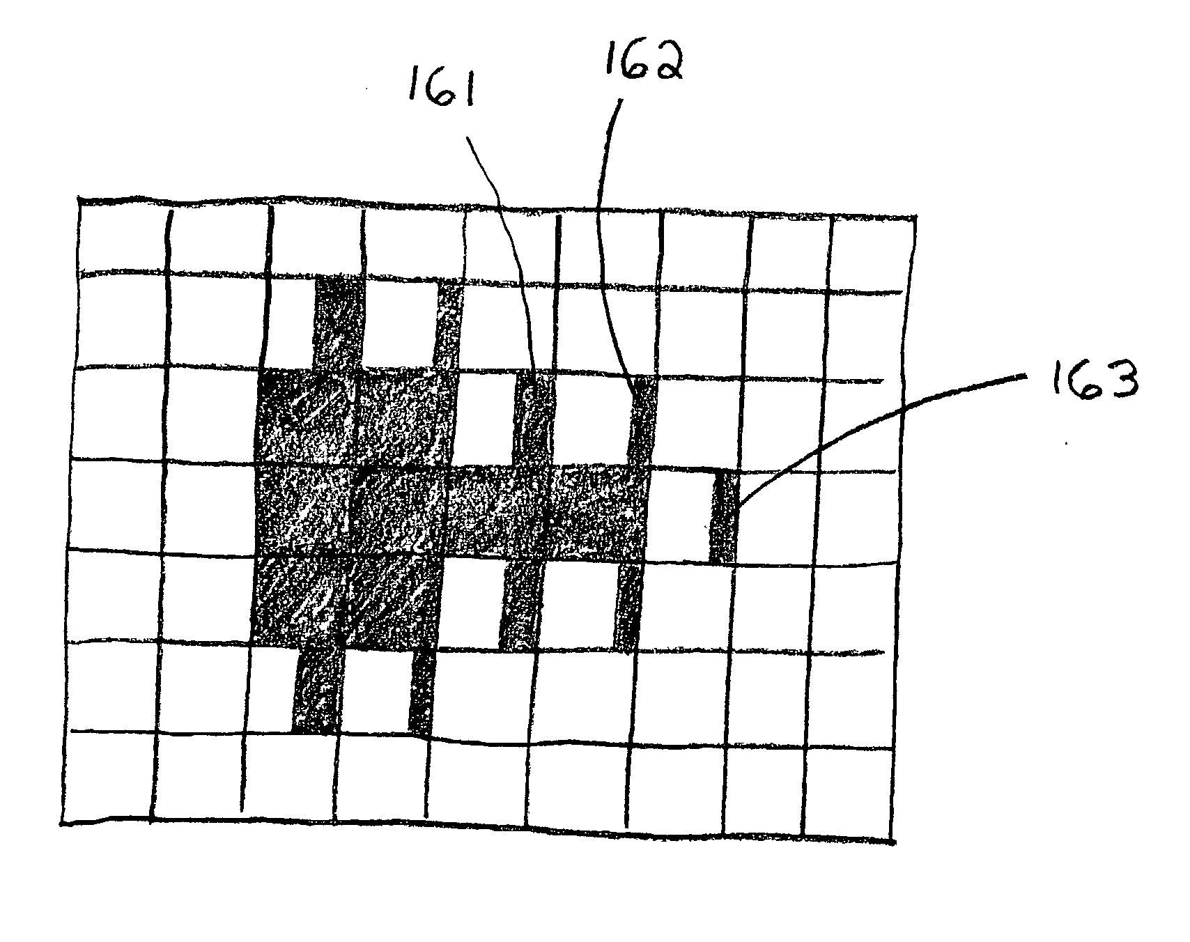
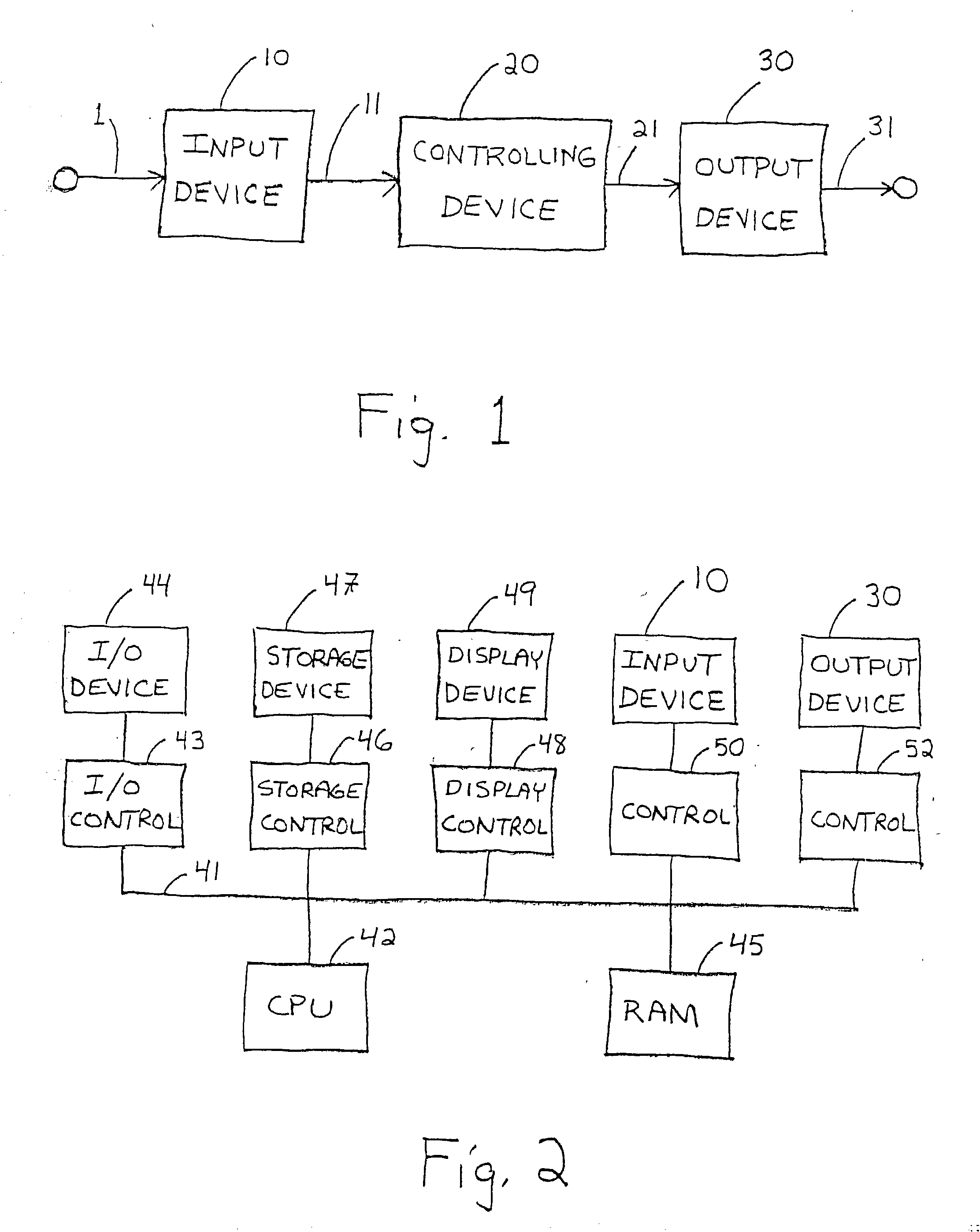
[0038] FIG. 1 illustrates major components in a typical image reproduction system. Input device 10 receives from path 1 signals representing an original image and generates along path 11 a rasterized representation of the original image. Controlling device 20 receives this representation from path 11 and, in response, generates along path 21 an output-device-dependent representation of the original image. Output device 30 receives this representation from path 21 and, in response, generates along path 31 a printed representation of the original image. The present invention is directed toward improving the perceived quality of the printed representation produced by the output device.

[0039] Input device 10 may be a software application capable of generating text or graphics images or, alternatively, may be an apparatus such as a scanner or camera. If input device 10 is a software application for creating images, the signals received from path 1 could represent commands ...


PUM


Abstract

The appearance of edges in an image is improved through precise placement of subpixels within pixel cells that are located on or near edges in an image. Image data is examined to identify a "target pixel" near the edge of an object that represents the object and is adjacent to a "background pixel" that represents only background. The target pixel may represent both the object and its background or it may represent the object only. A "second pixel", adjacent to the target pixel and representing the object, is also identified. The second pixel may represent both the object and its background or it may represent the object only. The target pixel's location with respect to the second pixel is analyzed to determine the placement of a subpixel within the target pixel cell and the placement of a subpixel within the second pixel cell, such that the edge of the object is well-defined and the density of the object is preserved. A vertical smoothing process can additionally be performed to improve further the appearance of edges in the image. The technique is particularly advantageous for printing a halftoned object represented by pixels that are not saturated.

Description

[0001] The invention relates to the processing of image data for the purpose of enhancing the appearance of an image as printed by a printing device such as a laser printer.[0002] A toner-transfer printing device such as a laser printer creates a printed image by printing an array of picture elements, referred to as pixels, on the print medium. Any image, whether text or graphics, to be printed by the printing device is represented in the form of a set of discrete pixels. Images such as photographs are, however, continuous analog representations of objects in the real world. Other types of images, including text and computer graphics images, may also contain representations of analog forms. In all cases, it is necessary to represent the desired image with discrete pixels if the image is to be printed by a toner-transfer printing device.[0003] One common representation is a raster or orthogonal grid of pixels. A rasterized image typically contains a large number of discrete pixels, e...

Claims


Application Information

Patent Timeline
Patent Type & Authority Applications(United States)
IPC IPC(8): B41J2/52G06F3/12G06K15/02G06K15/12G06T11/20
CPCG06K15/02G06K15/1822G06K15/18G06K15/1223
Inventor HUANG, JINCHENGGULERYUZ, ONURBHATTACHARJYA, ANOOPSHU, JOSEPH
Owner SEIKO EPSON CORP
Why Eureka
Try Eureka