
Method for backing up power supply of disk array device and system thereof

a technology of disk array device and power supply, which is applied in the direction of fault response, liquid/fluent solid measurement, instruments, etc., can solve the problems of unfavorable back-up of power supply, performance of back-up batteries, and design policy not fully applied to power supply of disk array devices

Inactive Publication Date: 2003-11-20
HITACHI LTD
View PDF21 Cites 78 Cited by
  • Summary
  • Abstract
  • Description
  • Claims
  • Application Information

AI Technical Summary

Problems solved by technology

However, such design policy has not been fully applied to power supply for the disk array device.
For example, in the above-mentioned conventional power supply system, failure of AC power is able to be backed-up by the batteries, but when the batteries themselves become inoperative due to such as failure, back up of power supply is not to be expected.
Performance of the back-up batteries is generally likely to be dependent on environmental factors such as temperature, vibration, and deterioration with time.
Thus, it becomes impossible to provide sufficient power backup since the performance of the batteries is insufficient.
However, such redundant system will substantially increase initial and running costs and also cause a problem of where to equip the batteries.
Therefore, a problem will arise when power failure occurs only in the disk drive but not in the disk controller.
One example of the problem is that even if power failure occurred at a certain disk drive, the disk controller is unable to detect the failure since the disk controller is unable to monitor the power condition of the disk drive.
More specifically, when data to be written into the disk drive with power failure is transferred to the disk controller from a host apparatus, the disk controller continues to accept the transferred data to be written since the disk controller is unable to monitor the power condition of the disk drive.
A problem is that the disk controller unable to detect power failure continues to transfer data to the disk drive which is operating on auxiliary power of limited capacity.
Furthermore, considering possibility of continuing data transfer, it is difficult to properly estimate the required capacity for auxiliary power supply.
In either case, it is hard to obtain proper capacity for a auxiliary power supply.

Method used


Image

  • Method for backing up power supply of disk array device and system thereof
  • Method for backing up power supply of disk array device and system thereof
  • Method for backing up power supply of disk array device and system thereof

Examples


second embodiment

OF THE INVENTION

[0055] The second embodiment of the present invention will be described hereinbelow with referring to the accompanying drawings.

[0056] As shown in FIG. 5, a disk array device 1000 (or a storage device, a disk subsystem) comprises a disk controller 100 and one or a plurality of disk drives 200. The disk controller 100 controls entire operation of the disk array device 1000. The disk controller 100 accepts request for data transfer from a host apparatus or requests a host apparatus to transmit and receive the data. The disk drive 200 including an HDD (Hard Disk Drive) writes / reads data to / from the HDD under control of the disk controller 100. The disk drive 200 may be equipped additionally as required so as to expand storage capacity of the disk array device 1000.

[0057] The disk controller 100 will be described hereinbelow. The disk controller 100 is comprised of a board containing electronic components for implementing its control functions. Among the electronic compo...


PUM


Abstract

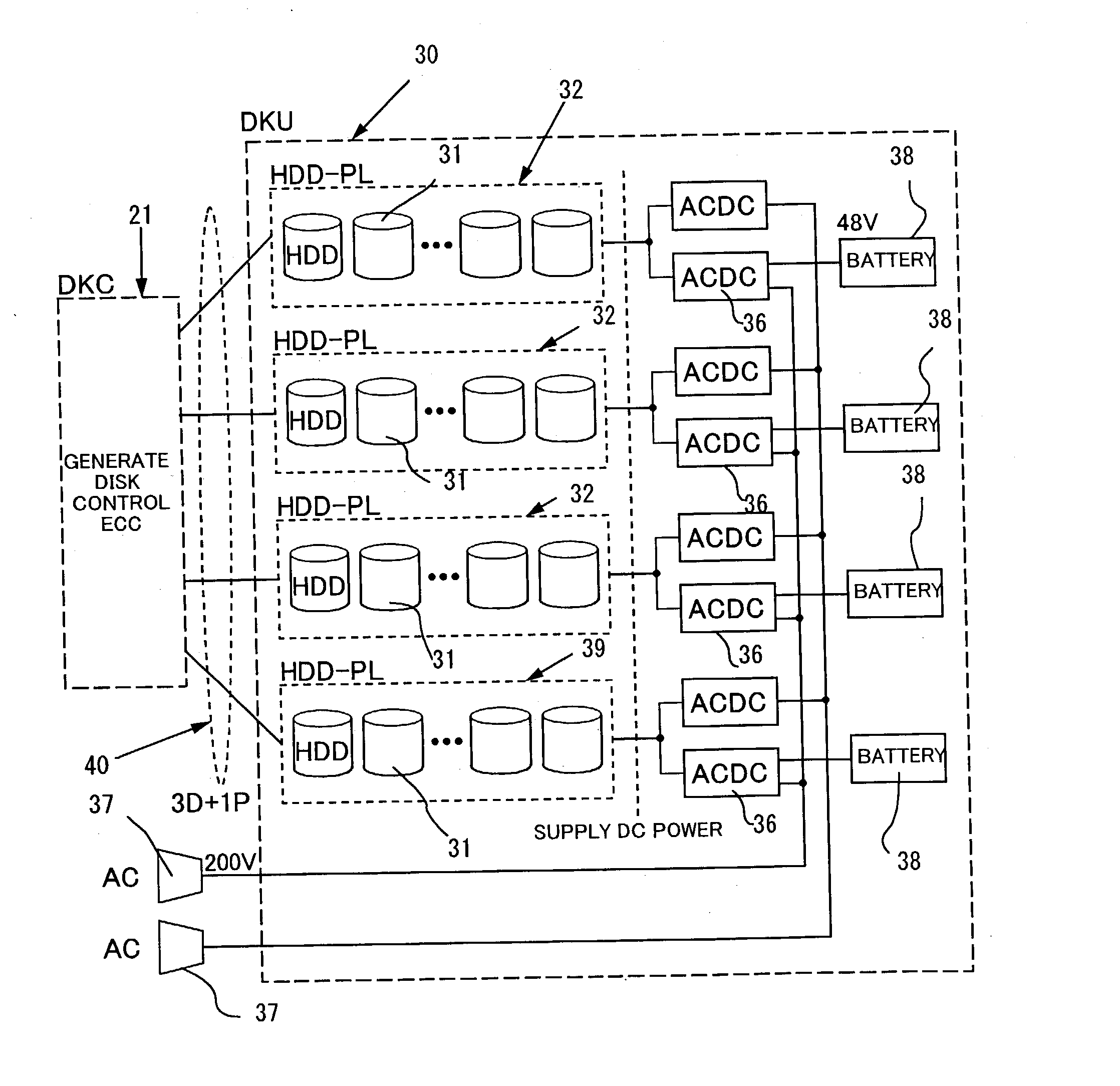
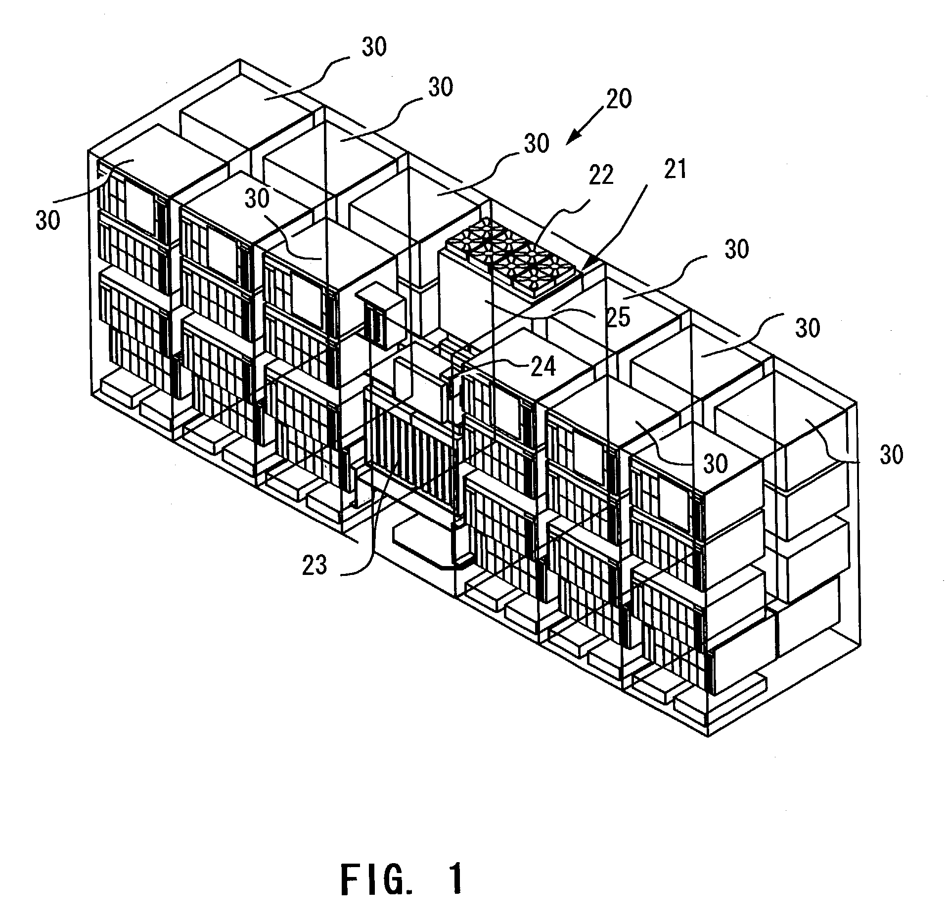
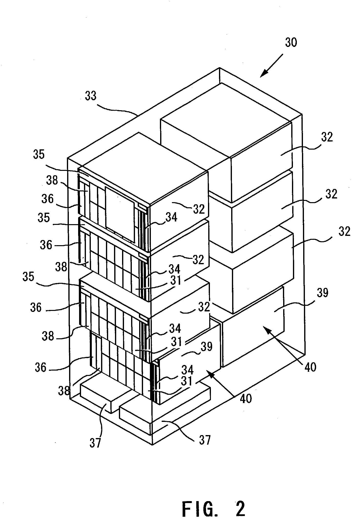
A disk array device having two or more disk units, each disk unit including at least one disk drive, at least either of said disk units having parity bits carrying data recovery information, comprises at least one backup battery provided for each of said disk unit.

Description

[0001] The present application claims priorities upon Japanese Patent Application No. 2002-128591 filed on Apr. 30, 2002 and Japanese Patent Application No. 2002-278902 filed on Sep. 25, 2002, which are herein incorporated by reference.[0002] 1. Field of the Invention[0003] The present invention is related to a method for backing up a power supply of a disk array device and a system therefor.[0004] 2. Description of the Related Art[0005] A disk array device has now come to be in use not only in a conventional machine room of stabilized condition but also in an ordinary office environment which may sometimes suffer continuing or instantaneous power failure and the like. In particular, as the disk array device is becoming more available through downsizing and employment of open architecture in CPU, the above situation is being spread. A typical configuration of power supply in a current disk array device is illustrated in FIG. 12 for example.[0006] A disk controller 11 (DKU) of the di...

Claims


Application Information

Patent Timeline
IPC IPC(8): G06F1/26G06F11/20
CPCG06F11/1076G06F11/2015G06F11/1088G06F2211/1071G06F2211/1009
Inventor FUKUMORI, MITSUOSUZUKI, HIROSHIMATSUSHIGE, HIROMIOGAWA, MASATOYOKOYAMA, TOMOKAZU
Owner HITACHI LTD
Learn More