Structure of a vehicle maintenance washing apparatus

a technology for washing equipment and vehicles, applied in the direction of vehicle cleaning, cleaning using liquids, instruments, etc., can solve the problems of increasing oil consumption, gasoline residue, and power loss of the engin

Inactive Publication Date: 2003-11-27
CHUAN TU TSUNG
View PDF10 Cites 9 Cited by
  • Summary
  • Abstract
  • Description
  • Claims
  • Application Information

AI Technical Summary

Problems solved by technology

The excessive temperature of the combustion chamber of a vehicle engine after driving will cause gasoline residue at the engine ejector, which will be formed into accumulated carbon.
The carbon hinders the atomizing gasoline even no gasoline is atomized and the power of the engine will be lost.
This will also increases the oil consumption and affects the quality of exhausted discharge.
Moreover, when the engine oil is changed, the exhausted oil in the engine may not be drained completely.
The run-in period of a new vehicle will generate alloy powder, and excessive heat of the engine while in driving will generate carbon particles and etc.
There may not only make the boss motion and the piston reciprocation movement to produce friction, but it may also increase the engine oil temperature, damaging the engine oil coating functioned to protect the engine.
Furthermore, a vehicle running for an extended period, despite periodic maintenance, the exhausted oil inside its torque rotary apparatus is unable to change totally.

Method used


Image

  • Structure of a vehicle maintenance washing apparatus
  • Structure of a vehicle maintenance washing apparatus
  • Structure of a vehicle maintenance washing apparatus

Examples


Embodiment Construction

[0014] The following descriptions are of exemplary embodiments only, and are not intended to limit the scope, applicability or configuration of the invention in any way. Rather, the following description provides a convenient illustration for implementing exemplary embodiments of the invention. Various changes to the described embodiments may be made in the function and arrangement of the elements described without departing from the scope of the invention as set forth in the appended claims.

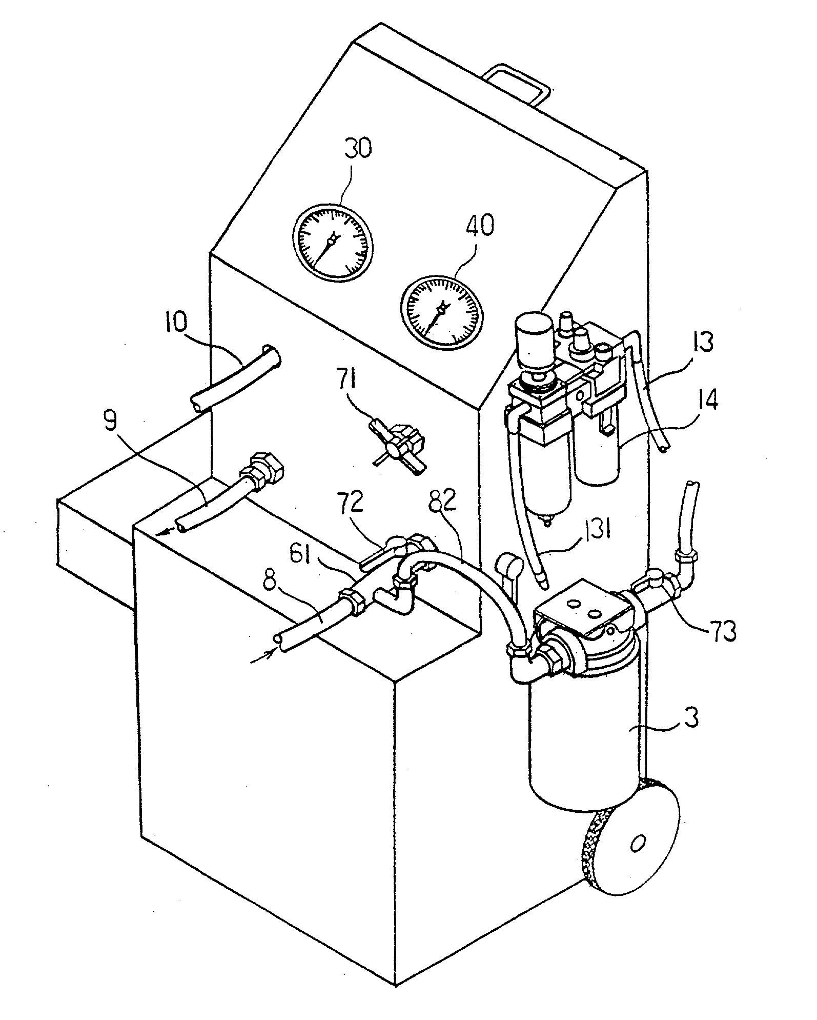
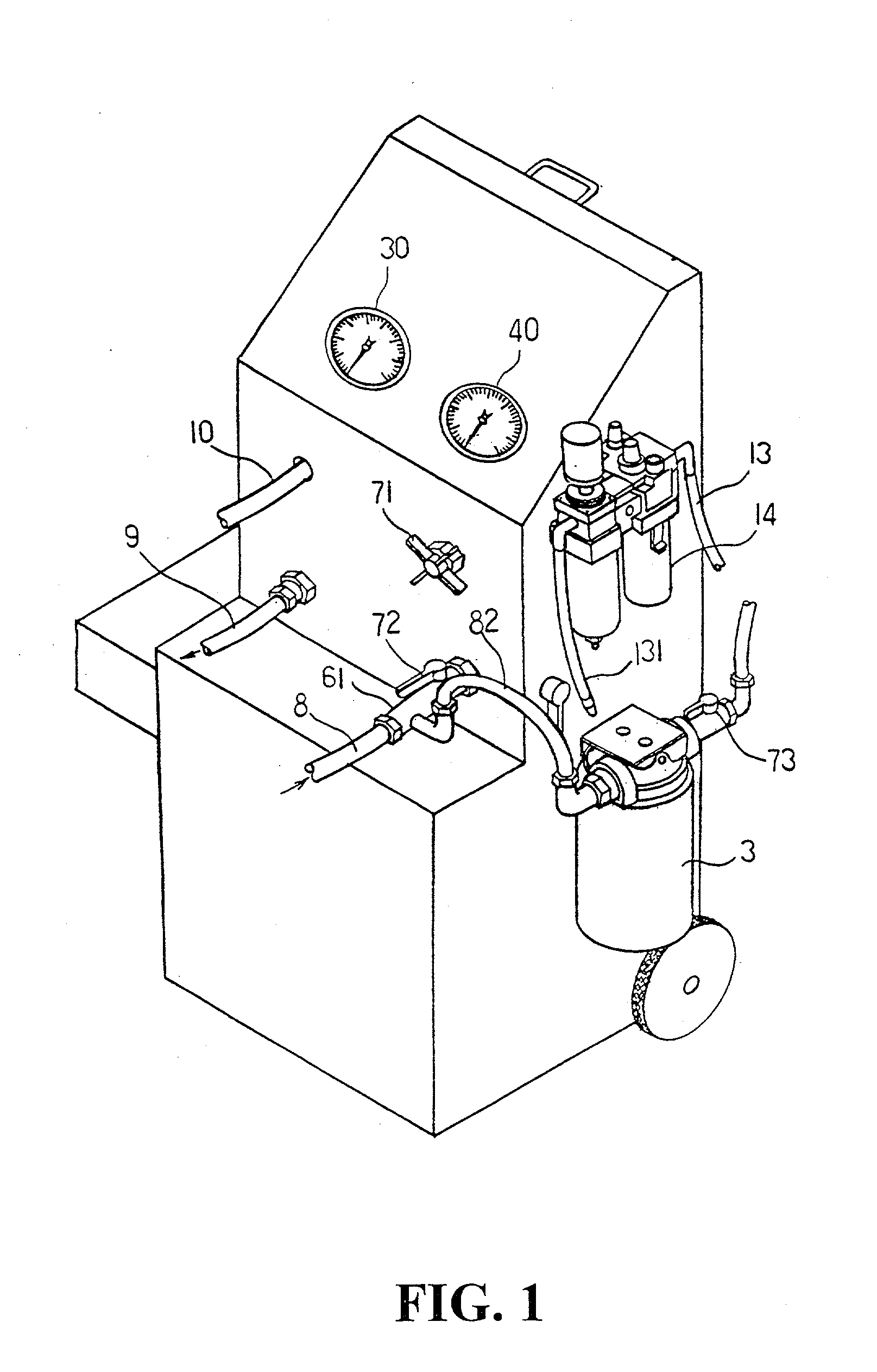
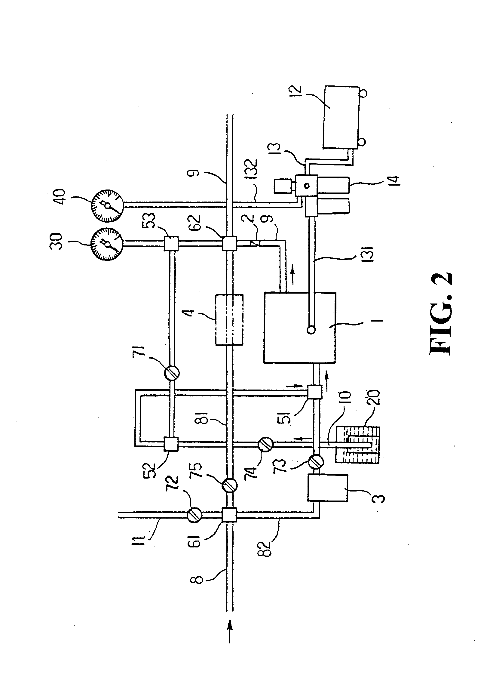
[0015] Referring to FIG. 1 and FIG. 2, an improved structure of a vehicle 110 maintenance washing apparatus of the present invention is disclosed. The apparatus comprises a pulse pump 1, a one check valve 2, an engine oil fine filter 3, a plurality of strainers 4, three units of three way joints 51, 52, 53, two units of four way joints 61, 62, and five units of butterfly valves 71, 72, 73, 74, 75 and other components. The apparatus may also be constructed and assembled with an inlet / outlet oil t...


PUM


Abstract

An improved structure of a vehicle maintenance and washing apparatus is disclosed and the apparatus comprises an air compressor with a pulse pump as a driven source, a one check valve, an engine oil fine filter, at least one or a plurality of strainers, a plurality of three way joints, a plurality of four way joints and a plurality of butterfly valves, characterized an inlet/outlet oil tube and a solvent tube are mounted thereof and the inlet oil tube passes the 1<st >four way joint and then divides into two routes, the 1<st >route inlet oil tube may or may not pass the strainer connecting the 2<nd >four way joint, and the 2<nd >route inlet oil tube passes the engine oil fine filter, the 3<rd >butterfly valve and the 1<st >three way joint and is then connected to the pulse pump, the solvent tube connected to the 4butterfly valve passes the 2<nd >three way joint and the 1<st >three way joint and enters the pulse pump outlet oil tube and from the pulse pump to the one check valve connecting the 2<nd >four way joint, and from the 2<nd >four way joint to the external, the inlet/outlet oil tube is connected to engine lubricating system, or ejector or auto gearshift box which needed to be cleaned.

Description

[0001] 1. Field of the Invention[0002] The present invention relates to an improved structure of vehicle maintenance and washing apparatus, and in particular, an apparatus with multi purposes. The apparatus can be used for washing an engine ejector, a lubricating system and an auto gearshift box.[0003] 2. Description of the Prior Art[0004] The excessive temperature of the combustion chamber of a vehicle engine after driving will cause gasoline residue at the engine ejector, which will be formed into accumulated carbon. The carbon hinders the atomizing gasoline even no gasoline is atomized and the power of the engine will be lost. This will also increases the oil consumption and affects the quality of exhausted discharge. Moreover, when the engine oil is changed, the exhausted oil in the engine may not be drained completely. The run-in period of a new vehicle will generate alloy powder, and excessive heat of the engine while in driving will generate carbon particles and etc. There ma...

Claims


Application Information

Patent Timeline
Patent Type & Authority Applications(United States)
IPC IPC(8): B08B9/00B08B9/02B60S3/00F02M65/00
CPCB08B9/00B08B9/0321F02M65/007B60S3/00B08B9/0325
Inventor CHUAN, TU TSUNG
Owner CHUAN TU TSUNG
Why Eureka
Try Eureka