Tension indicator for cardiac support device and method therefore
a technology of a valvular support device and a pulsating indicator, which is applied in the field of pulsating indicator for a cardiac support device and a method therefore, can solve the problems of fatigue of the afflicted patient, inability to perform even simple exerting tasks, and inability to adequately supply blood to the heart so that the heart is so large that it cannot adequately supply blood,
- Summary
- Abstract
- Description
- Claims
- Application Information
AI Technical Summary
Problems solved by technology
Method used
Image
Examples
second embodiment
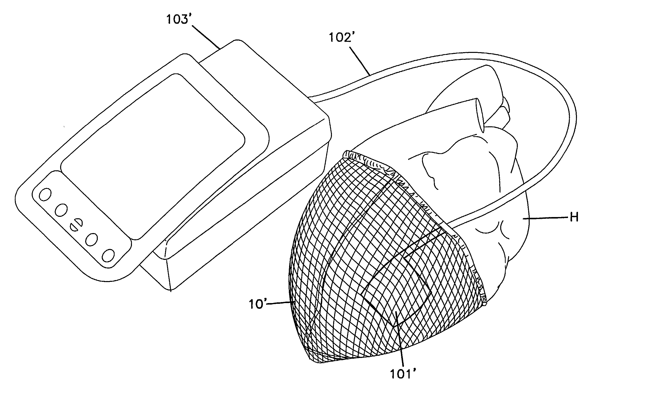
[0044] The jacket 10, 10' is an enclosed material having upper and lower ends 12, 12', 14, 14'. The jacket 10, 10' defines an internal volume 16, 16' which is completely enclosed but for the open ends 12, 12' and 14'. In the embodiment of FIG. 3, lower end 14 is closed. In the embodiment of FIG. 4, lower end 14' is open. In both embodiments, upper ends 12 and 12' are open. Throughout this description, the embodiment of FIG. 3 will be discussed. Elements in common between the embodiments of FIGS. 3 and 4 are numbered identically with the addition of an apostrophe to distinguish the second embodiment and such elements need not be separately discussed.
[0045] The jacket 10 is dimensioned with respect to a heart H to be treated. Specifically, the jacket 10 is sized for the heart H to be supported within the volume 16. The jacket 10 can be slipped around the heart H. The jacket 10 has a length L between the upper and lower ends 12, 14, sufficient for the jacket 10 to support the lower por...
working examples
Example 1
[0107] Bladders were obtained from PMT (Minneapolis, Minn.). 1".O slashed. and 1".times.3" oblong bladders were filled several milliliters of saline. The tube connection was cut and a Millar pressure-measuring catheter was inserted into the opening such that the tip of the catheter was in contact with the saline in the bladder. The bladder was then sealed around the Millar catheter.
[0108] The tension indicator was intra-operatively positioned between a jacket 10 and the epicardial surface of a dog heart. Baseline readings (of the tension indicator) were taken prior to tensioning the jacket.
[0109] The jacket was tensioned by gathering excess material and the pressure was monitored using the tension indicator and compared to the baseline measurements. The pressure measurement from the bladder corresponded to the pressure applied by the jacket.
example 2
[0110] An alternate bladder design (provided by Dr. Tyberg, University of Calgary, Alberta, Calif.) was also tested on dogs, pigs and sheep using essentially the same procedure described in Example 1. The bladder used in this experiment is constructed using a square silastic pillow (approximately 1".times.1") having a small diameter (approximately 3 mm) tube penetrating one edge of the pillow. The tube provides the access for a pressure transducer such as a Millar catheter.
PUM
 Abstract
Description
Claims
Application Information
 - R&D
- Intellectual Property
- Life Sciences
- Materials
- Tech Scout
- Unparalleled Data Quality
- Higher Quality Content
- 60% Fewer Hallucinations
Browse by: Latest US Patents, China's latest patents, Technical Efficacy Thesaurus, Application Domain, Technology Topic, Popular Technical Reports.
© 2025 PatSnap. All rights reserved.Legal|Privacy policy|Modern Slavery Act Transparency Statement|Sitemap|About US| Contact US: help@patsnap.com


