Audio coding system using spectral hole filling

a coding system and spectral hole technology, applied in the field of audio coding system using spectral hole filling, can solve the problems of degrading not working as well in the wider band, and fairly well working technique, so as to avoid or reduce degradation, improve the perceived quality of the audio signal

Active Publication Date: 2003-12-18
DOLBY LAB LICENSING CORP
View PDF43 Cites 295 Cited by
  • Summary
  • Abstract
  • Description
  • Claims
  • Application Information

AI Technical Summary

Benefits of technology

0010] It is an object of the present invention to improve the perceived quality of audio signals obtained f...

Problems solved by technology

This technique works fairly well for narrow bands but does not work as well for wider bands when information capacity requirements constrain the coding system to use a relatively coarse quantizing resolution.
Unfortunately, the existence of many quantized-to-zero (QTZ) spectral components in an encoded signal can degrade the perceived quality of the audio signal even if the resulting quantization noise is kept low enough to be deemed inaudible or psychoacoustically masked by spectral components in the signal.
The first cause is the fact that the quantization noise may not be inaudible because the level of psychoacoustic masking is less than what is predicted by the psychoacoustic model used to determine the quantizing resolution.
A second cause is the fact that the creation of many QTZ s...

Method used


Image

  • Audio coding system using spectral hole filling
  • Audio coding system using spectral hole filling
  • Audio coding system using spectral hole filling

Examples


Embodiment Construction

[0032] A. Overview

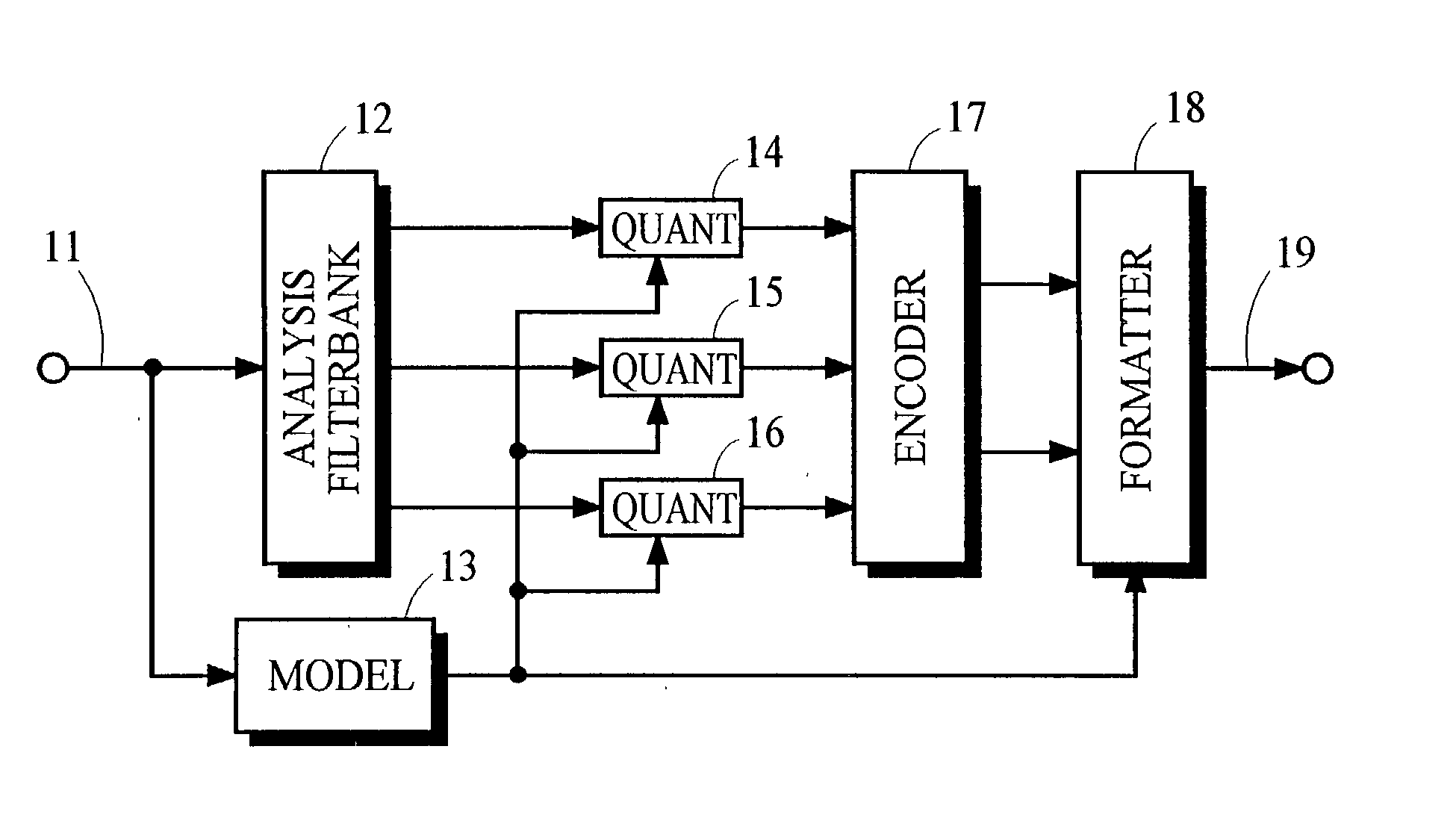
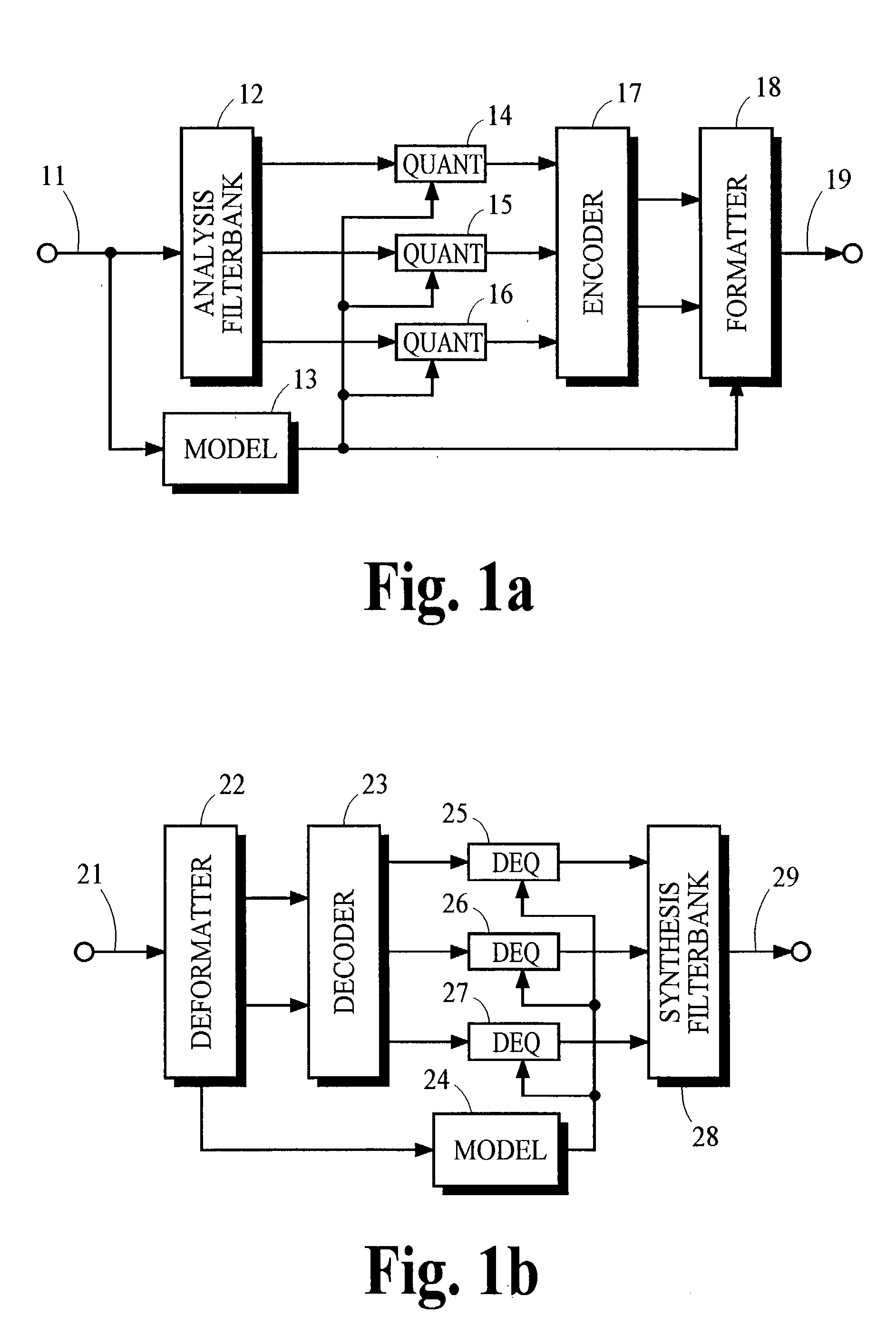
[0033] Various aspects of the present invention may be incorporated into a wide variety of signal processing methods and devices including devices like those illustrated in FIGS. 1a and 1b. Some aspects may be carried out by processing performed in only a decoding method or device. Other aspects require cooperative processing performed in both encoding as well as decoding methods or devices. A description of processes that may be used to carry out these various aspects of the present invention is provided below following an overview of typical devices that may be used to perform these processes.

[0034] 1. Encoder

[0035] FIG. 1a illustrates one implementation of a split-band audio encoder in which the analysis filterbank 12 receives from the path 11 audio information representing an audio signal and, in response, provides digital information that represents frequency subbands of the audio signal. The digital information in each of the frequency subbands is quantized b...


PUM


Abstract

Audio coding processes like quantization can cause spectral components of an encoded audio signal to be set to zero, creating spectral holes in the signal. These spectral holes can degrade the perceived quality of audio signals that are reproduced by audio coding systems. An improved decoder avoids or reduces the degradation by filling the spectral holes with synthesized spectral components. An improved encoder may also be used to realize further improvements in the decoder.

Description

[0001] The present invention is related generally to audio coding systems, and is related more specifically to improving the perceived quality of the audio signals obtained from audio coding systems.[0002] Audio coding systems are used to encode an audio signal into an encoded signal that is suitable for transmission or storage, and then subsequently receive or retrieve the encoded signal and decode it to obtain a version of the original audio signal for playback. Perceptual audio coding systems attempt to encode an audio signal into an encoded signal that has lower information capacity requirements than the original audio signal, and then subsequently decode the encoded signal to provide an output that is perceptually indistinguishable from the original audio signal. One example of a perceptual audio coding system is described in the Advanced Television Standards Committee (ATSC) A52 document (1994), which is referred to as Dolby AC-3. Another example is described in Bosi et al., "...

Claims


Application Information

Patent Timeline
IPC IPC(8): G10L19/02G10L19/028G10L21/02H03M7/30
CPCG10L21/038G10L19/035G10L21/02G10L19/02
Inventor TRUMAN, MICHAEL MEADDAVIDSON, GRANT ALLENFELLERS, MATTHEW CONRADVINTON, MARK STUARTWATSON, MATTHEW AUBREYROBINSON, CHARLES QUITO
Owner DOLBY LAB LICENSING CORP
Why Eureka
Try Eureka