System and method for isolating network clients

Active Publication Date: 2004-01-01
AVAGO TECH INT SALES PTE LTD
View PDF27 Cites 91 Cited by
  • Summary
  • Abstract
  • Description
  • Claims
  • Application Information

AI Technical Summary

Problems solved by technology

One disadvantage of a port-configuration VLAN is that a separate VLAN must be used for each port on the DSLAM 102 in order to provide security and isolation to each subscriber connected thereto.
Therefore, un

Method used


Image

  • System and method for isolating network clients
  • System and method for isolating network clients
  • System and method for isolating network clients

Examples


Embodiment Construction

:

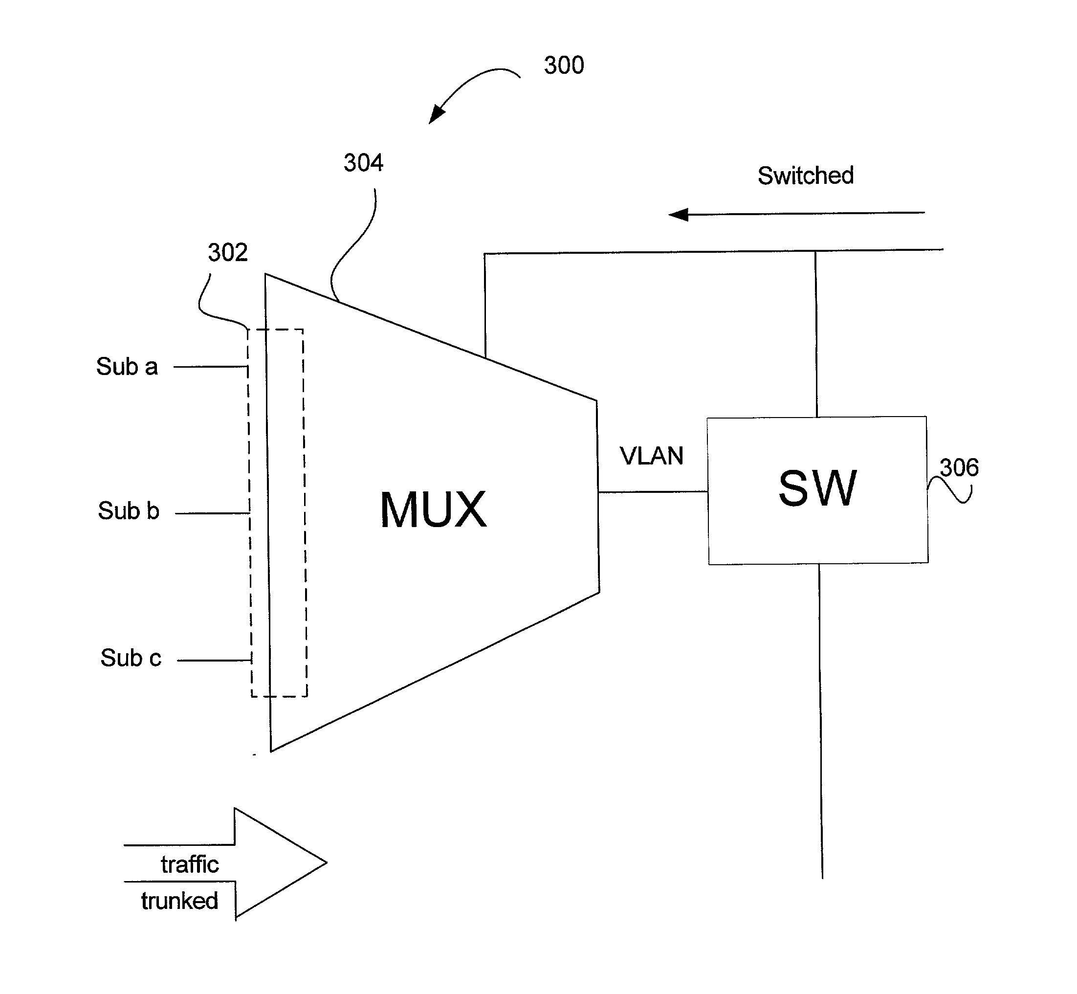
[0021] FIG. 3 is a block diagram of a network device according to an embodiment of the present invention. Device 300 is referred to herein as a switch-MUX, because in this embodiment it has attributes of an Ethernet switch combined with a multiplexer. However, the term MUX is not meant to be limited to a multiplexer, and the term MUX may also refer to aggregation circuits and logic that may or may not have processing ability or intelligence built-in.

[0022] Switch-MUX 300 includes a plurality of ports 302 for connecting to network clients, such as subscribers Sub a-Sub c. Network ports 302 may include any layer-1 PHYs or transceivers configured to transmit and receive data packets. Ports 302 are connected to a multiplexer MUX 304 which aggregates or trunks signals input from network clients Sub a-Sub c. The output of MUX 304 is input into a switching unit 306 to be switched to a destination. MUX 304 may be a discrete multiplexer component or circuit, or may be an IC.

[0023] Switching...


PUM


Abstract

A network device includes at least one first network port, at least one second network port, a MUX unit and a switching unit. The MUX unit is connected to the at least one first network port. The MUX unit includes a trunk circuit and an output. The trunk circuit is configured to aggregate data packets received at the at least one first port into a trunk group and to output trunked data packets to the output. The switching unit is connected to the output of the MUX unit and to the at least one second network port. The switching unit is configured to switch the trunked data packets to the at least one second network port.

Description

[0001] 1. Field of the Invention[0002] This invention relates to systems and methods for switching data within a data communications network. In particular, the present invention is related to systems and methods of isolating a group of network clients connected to a network device, such as a switch, router, repeater, etc.[0003] 2. Description of the Related Art[0004] Over the last several years, the proliferation of the Internet has had a significant impact on many industries, especially the computer industry. The Internet has grown into an enormous worldwide system of computer networks to which virtually any large or small computer network, or individual computer, may be connected. Internet access is typically obtained via an Internet Service Provider (ISP). ISPs provide access to the Internet for their customers usually through membership subscriptions in conjunction with service level agreements (SLAs). ISPs make at least a portion of their income on service fees such as subscri...

Claims


Application Information

Patent Timeline
IPC IPC(8): H04L12/12H04L12/46H04L12/56
CPCH04L12/12H04L12/4641Y02B60/35Y02B60/33Y02B60/34H04L45/245Y02D30/50
Inventor WONG, DAVID
Owner AVAGO TECH INT SALES PTE LTD
Why Eureka
Try Eureka