Land grid array connector with canted electrical terminals

a technology of canted electrical terminals and land grid arrays, which is applied in the direction of coupling contact members, fixed connections, coupling device connections, etc., can solve the problem that the normal force of contact between the contact and the circuit pad is generally not large, and achieves the effect of reducing the normal force of conta

Inactive Publication Date: 2004-01-01
HON HAI PRECISION IND CO LTD
View PDF8 Cites 44 Cited by
  • Summary
  • Abstract
  • Description
  • Claims
  • Application Information

AI Technical Summary

Problems solved by technology

Due to this configuration, contact normal force acting on the mating interface between the contact and the circuit pad is generally not large enough to maintain a reliable connection therebetween.
This is especially so when the connector is used in harsh environments in which corrosion and contaminants degenerate the mating interface.

Method used


Image

  • Land grid array connector with canted electrical terminals
  • Land grid array connector with canted electrical terminals
  • Land grid array connector with canted electrical terminals

Examples


Embodiment Construction

[0017] Reference will now be made to the drawings to describe the present invention in detail.

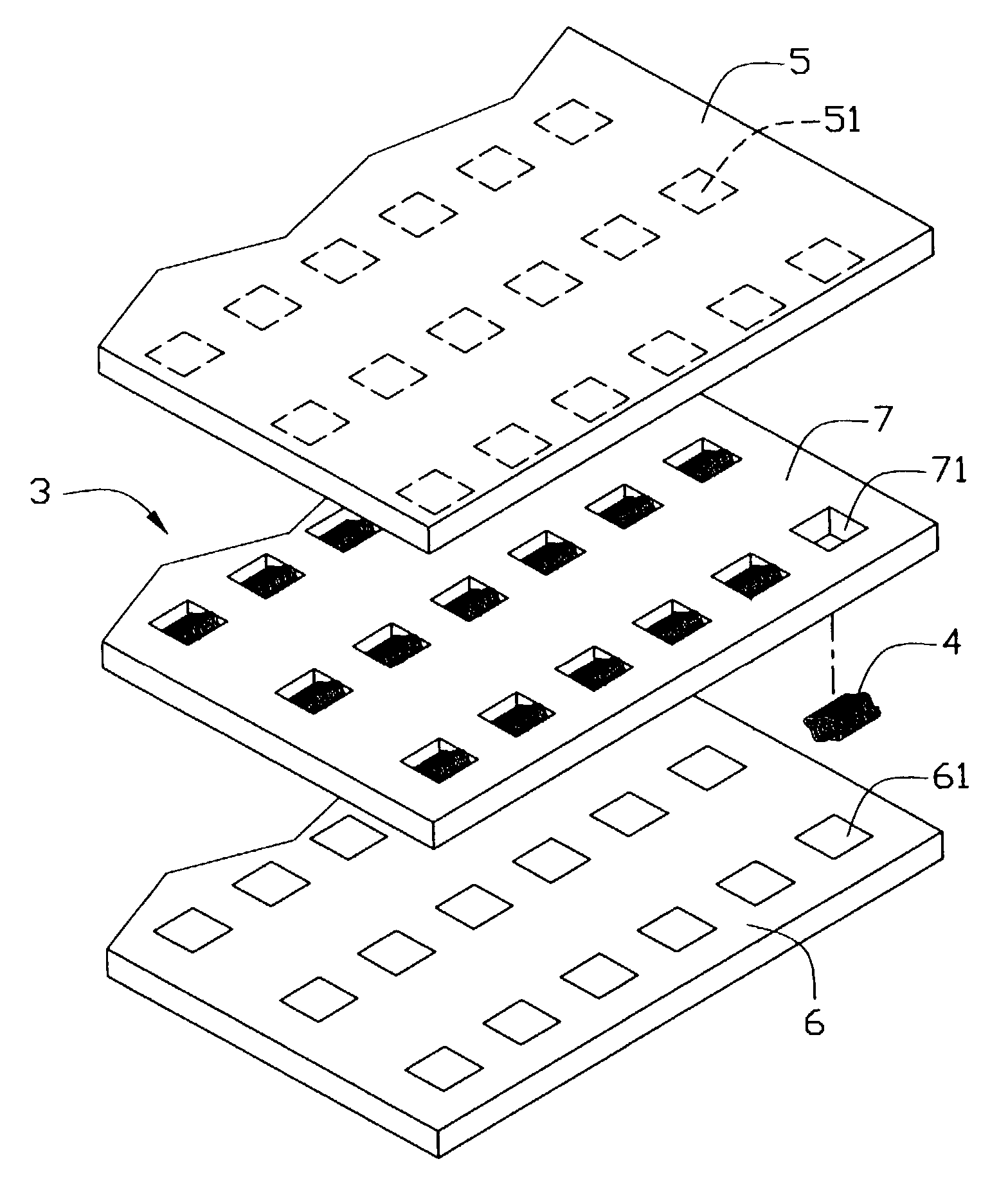
[0018] Referring to FIGS. 1 and 2, an electrical connector 3 in accordance with a preferred embodiment of the present invention comprises a carrier plate 7 having a multiplicity of openings 71 defined therethrough, and a multiplicity of canted coil spring electrical terminals 4 respectively received in the openings 71.

[0019] The carrier plate 7 may be of any suitable insulative material. Alternatively, if the carrier plate 7 is formed from a conductive material such as steel, the conductive material must coated with an insulative layer. The openings 71 of the preferred embodiment are square openings. The openings 71 may alternatively have another shape; for example, they may be rectangular openings. A shape and size of the openings 71 correspond to a shape and size of circuit pads 51, 61 of respective circuit substrates 5, 6.

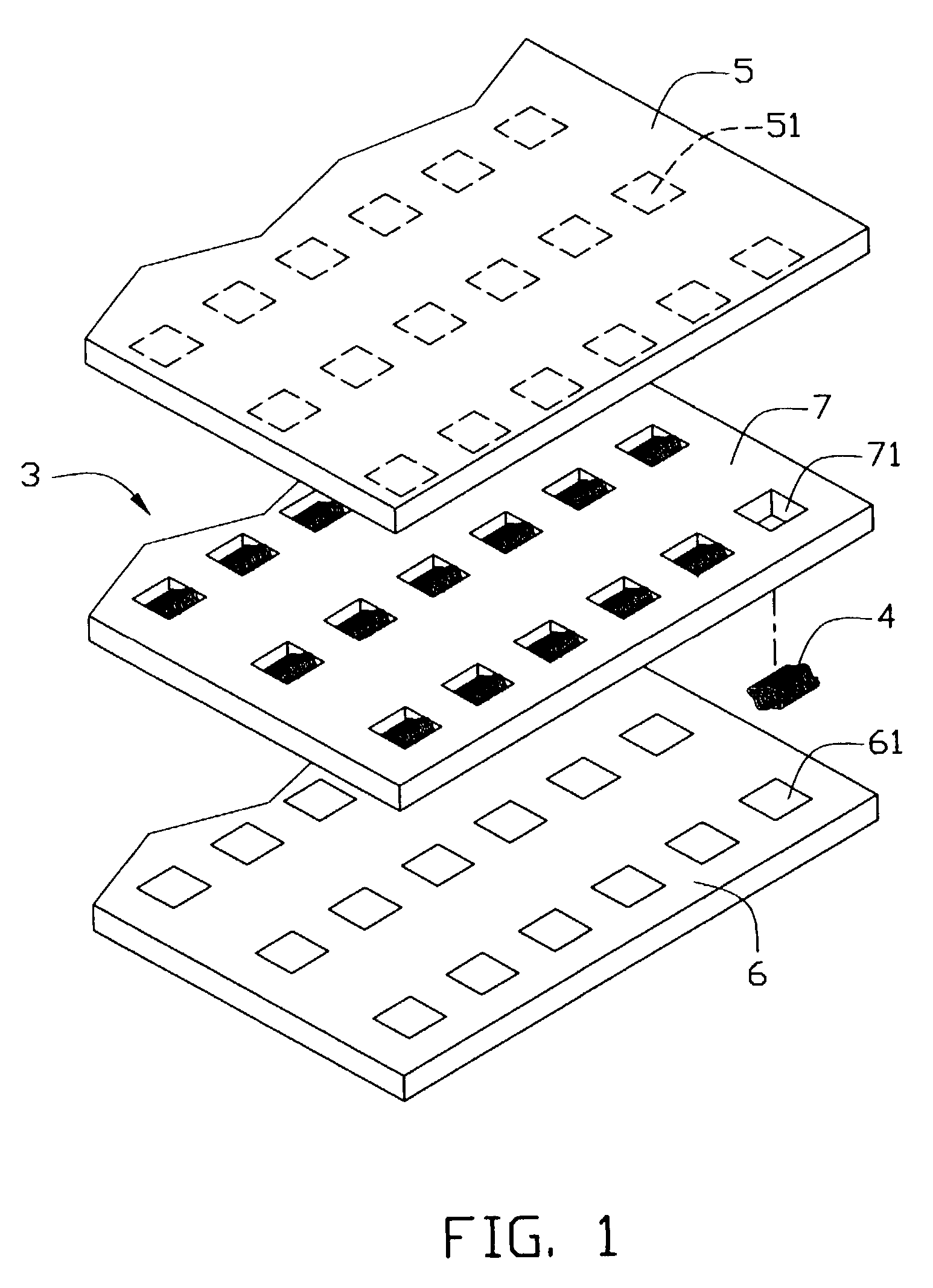
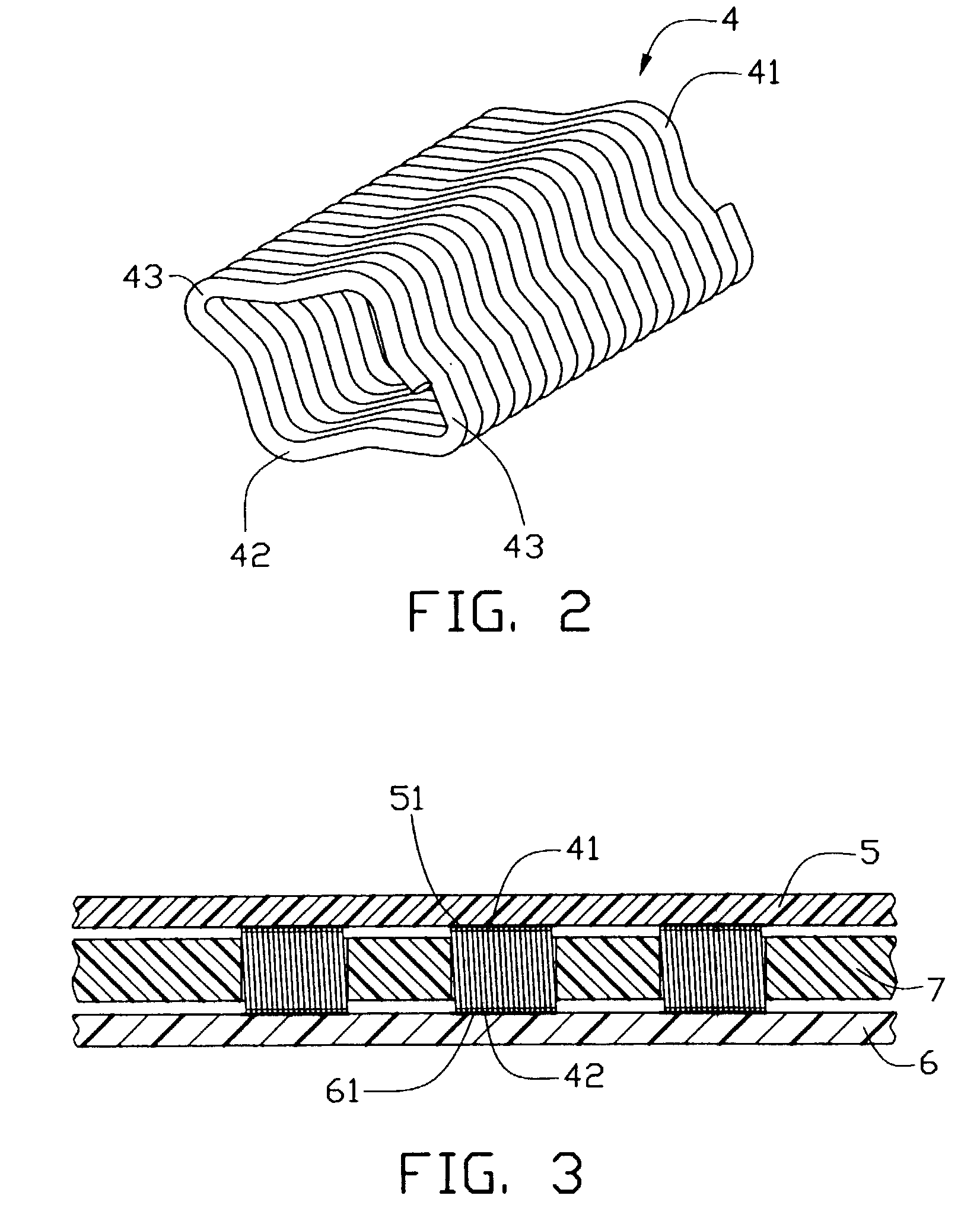
[0020] Each terminal 4 is cut from a length of electrically conduc...


PUM


Abstract

An electrical connector (3) for electrical interconnection of a pair of circuit substrates (5, 6) includes a carrier plate (7) defining a plurality of openings (71) retaining electrical terminals (4) therein. The openings correspond to circuit pads (51, 61) on the circuit substrates. Each terminal generally has a canted coil spring configuration. Each loop of the canted coil spring configuration has curved contact portions (41, 42) for bearing against corresponding circuit pads, engaging portions (43) for engaging side walls of the carrier plate at a corresponding opening, and connection portions interconnecting the curved contact portions and the engaging portions. Radiuses of curvature of the curved contact portions are less than radiuses of curvature of the connection portions of each loop. Each loop closely abuts an adjacent loop of the terminal. Relatively large contact normal force is thus attained when the curved contact portions bear against the corresponding circuit pads.

Description

[0001] 1. Field of the Invention[0002] The present invention relates to an electrical connector such as a land grid array (LGA) connector having canted electrical terminals for electrically interconnecting two spaced apart circuit substrates.[0003] 2. Description of Related Art[0004] Electrical connectors for electrically interconnecting two circuit substrates have been devised since as early as July, 1970. For example, U.S. Pat. No. 3,638,163 granted to Loosme disclosed a cylindrical, insulative body having a multiplicity of spaced apart conductive contacts wrapped therearound for being placed between parallel substrates having conductive strips thereon. The strips were thereby electrically interconnected through the contacts.[0005] Subsequently, U.S. Pat. No. 3,795,884 granted to Y. Kotaka disclosed a connector comprising an insulative block having coil springs encapsulated therein. Each coil was electrically isolated from adjacent coils by an axial cut in one surface of the block...

Claims


Application Information

Patent Timeline
Patent Type & Authority Applications(United States)
IPC IPC(8): H01R13/24H05K1/11H01R4/48H05K1/14
CPCH01R13/2421H01R12/7082H01R12/714H01R12/52
Inventor MASAO, OKITASZU, MING-LUN
Owner HON HAI PRECISION IND CO LTD
Why Eureka
Try Eureka