Self-attaching elastic cord

a self-attaching, elastic cord technology, applied in the direction of snap fasteners, buckles, press-button fasteners, etc., can solve the problems of insufficient pressure on the fastener to continue securing objects, limited binding possibilities, and user's inability to have unlimited flexibility to bind strips

Inactive Publication Date: 2004-01-15
SIMON JAMES S
View PDF0 Cites 19 Cited by
  • Summary
  • Abstract
  • Description
  • Claims
  • Application Information

AI Technical Summary

Problems solved by technology

However, the binding possibilities were limited due to the need for two separate strips.
While this type of strip adds the ability to bind to itself when one side comes into contact with the other side, the user does not have unlimited flexibility to bind the strip despite the orientation of the strip.
Due to the non-compliant nature of the strip or rope implem

Method used


Image

  • Self-attaching elastic cord
  • Self-attaching elastic cord
  • Self-attaching elastic cord

Examples


Embodiment Construction

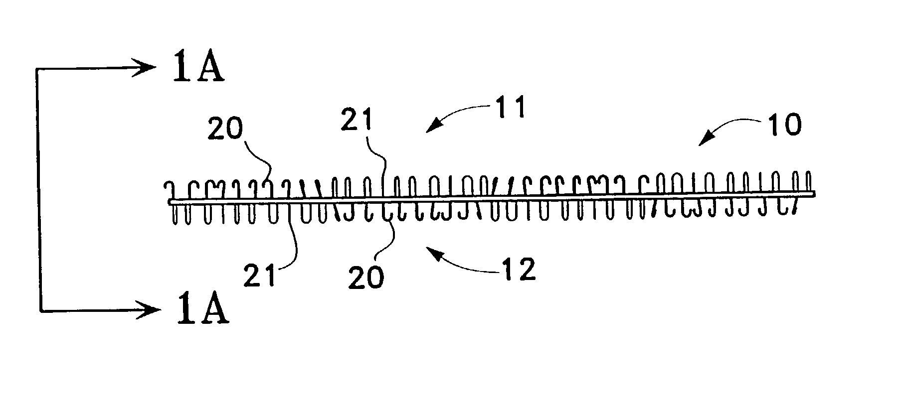
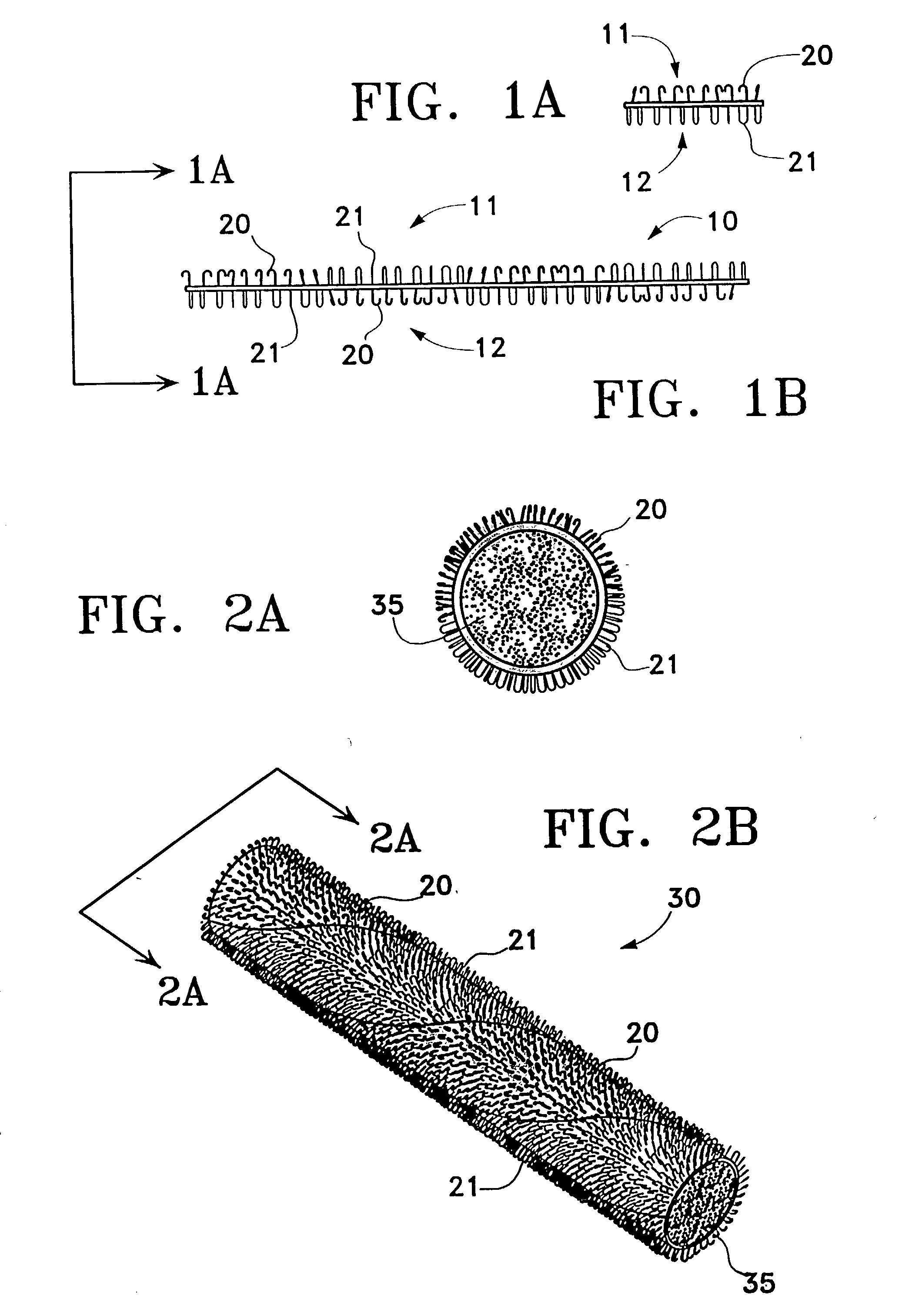
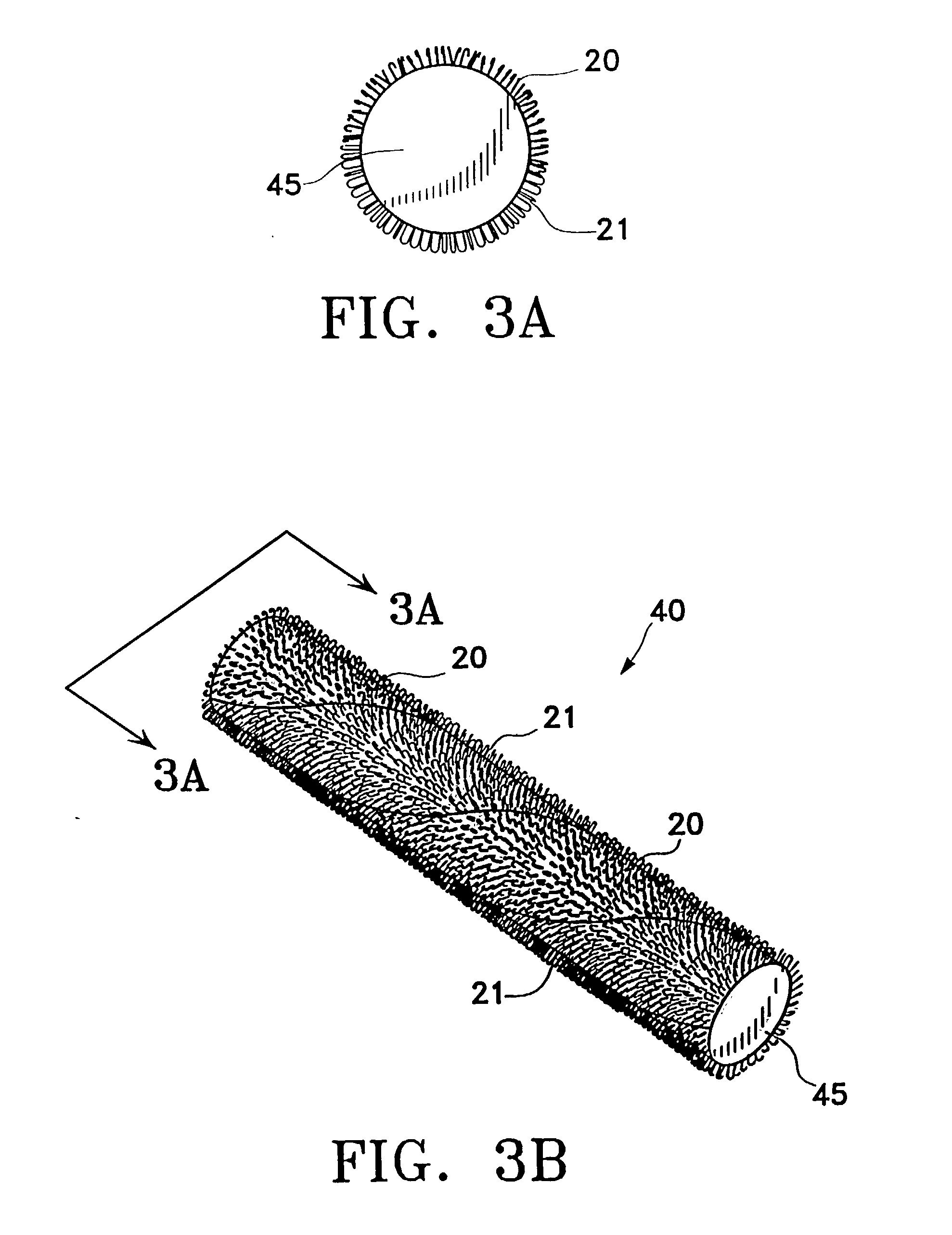
[0034] Throughout these figures, reference number 20 is used to generally designate hook material. Numeral 21 is used to generally designate loop material.

[0035] FIGS. 1A and 1B show a variation of the binding member of the present invention. FIG. 1A illustrates a cross sectional view of an elastic strip 10 that contains hook material 20 on face 11 and loop material 21 on face 12. As depicted in FIG. 1B on face 11, there is an area of hook material 20 and a generally adjacent area of loop material 21. The generally adjacent regions are also found on a second variation of the binding member as illustrated in FIGS. 2A and 2B. These figures show an elastic cord 30 with hook material 20 and loop material 21 generally adjacent on the surface 35 of the elastic cord 30. FIG. 2A illustrates a cross sectional view of the elastic cord 30 showing hook material 20 on one part and loop material 21 on the other part of the elastic cord surface 35. FIG. 2B depicts a side view of elastic cord 30 sh...


PUM


Abstract

A binding device comprising an elongated elastic member that contains at least one region of loop material generally adjacent to at least one region of hook material. The regions of different material allow binding when the loop material of the binding member comes in contact with the hook material. The elastic member is flexible and may bend back on itself to engage the hook and loop material. For example, an elastic self-attaching cord may include a surface that contains regions of loop material generally adjacent to hook material at evenly spaced intervals or placed at random intervals. Another examples are a tube or strip binding member. The elastic tube or strip binding device also contains loop material generally adjacent to hook material positioned on the surface of the tube or strip.

Description

[0001] The present invention relates to an elastic cord or similar material, which is capable of easily securing itself about an object without the need for knots or similar manipulation of the cord. In particular, the present invention relates to an elastic self-attaching binding instrument that utilizes hook and loop regions on the surface of an elastic body to secure itself to itself about an object. By having regions of loop material and hook material on the surface of the binding device, the binding member can form multiple binding positions.DESCRIPTION OF RELATED ART[0002] Mating fabrics, such as loop material and hook material, e.g. "VELCRO", provide the user with the capability to form a strong bond that can nevertheless be broken by peeling the materials apart. The binding occurs when the hook material comes into contact with the loop material. Mating fabrics of loop material and hook material are disclosed in U.S. Pat. Nos. 2,717,437 and 3,009,235 granted to G.de Mestral w...

Claims


Application Information

Patent Timeline
IPC IPC(8): A44B18/00
CPCY10T24/2708A44B18/0088
Inventor SIMON, JAMES S.
Owner SIMON JAMES S
Why Eureka
Try Eureka