Fuel injection system for an internal combustion engine

a fuel injection system and internal combustion engine technology, applied in the direction of machines/engines, positive displacement liquid engines, electric control, etc., can solve the problems of limited drive power, high drive power, and severe heating of fuel pumped, so as to reduce the drive power required for the prefeed pump and reduce the effect of severe heating of fuel and less complicated sealing

Inactive Publication Date: 2004-01-15
ROBERT BOSCH GMBH
View PDF9 Cites 23 Cited by
  • Summary
  • Abstract
  • Description
  • Claims
  • Application Information

AI Technical Summary

Benefits of technology

0005] The fuel injection system of the invention has the advantage over the prior art that the drive power required for the prefeed pump can be reduced, and severe heating of the fuel does not occur, since only the fuel quantity required is pumped by the prefeed pump. Moreover, the metering device is not subjected to the pressure generated by the prefeed pump and can therefore be sealed off less complicatedly.

Problems solved by technology

As a result, although the requisite drive power for the high-pressure fuel pump is limited because the high-pressure fuel pump pumps only the fuel quantity actually required into the reservoir, nevertheless, as a rule the prefeed pump pumps an excessive fuel quantity, which is returned again.
This requires high drive power for the prefeed pump, and the fuel pumped is severely heated.
Moreover, the fuel metering device is subjected to the pressure generated by the prefeed pump and must be correspondingly complicatedly sealed off.

Method used


Image

  • Fuel injection system for an internal combustion engine
  • Fuel injection system for an internal combustion engine
  • Fuel injection system for an internal combustion engine

Examples


Embodiment Construction

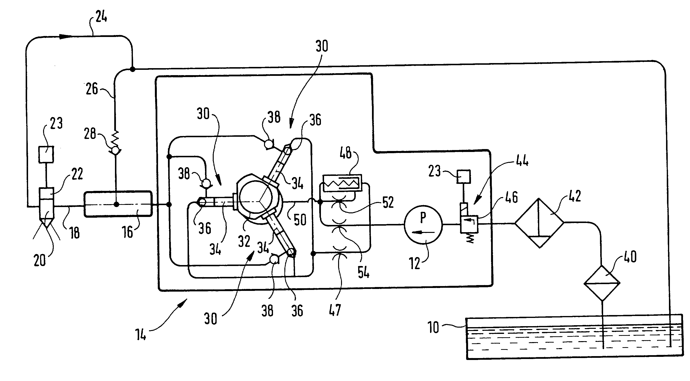
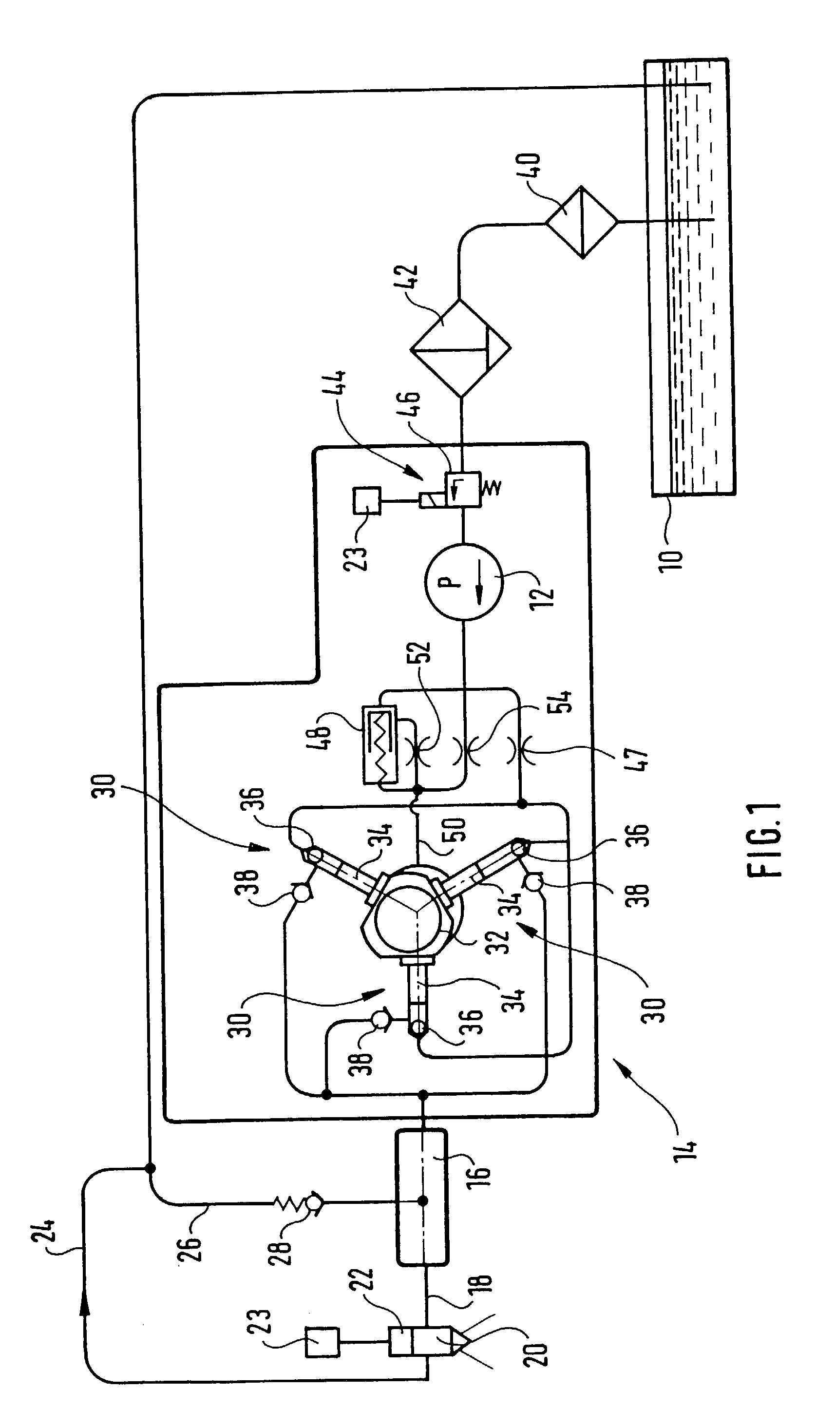
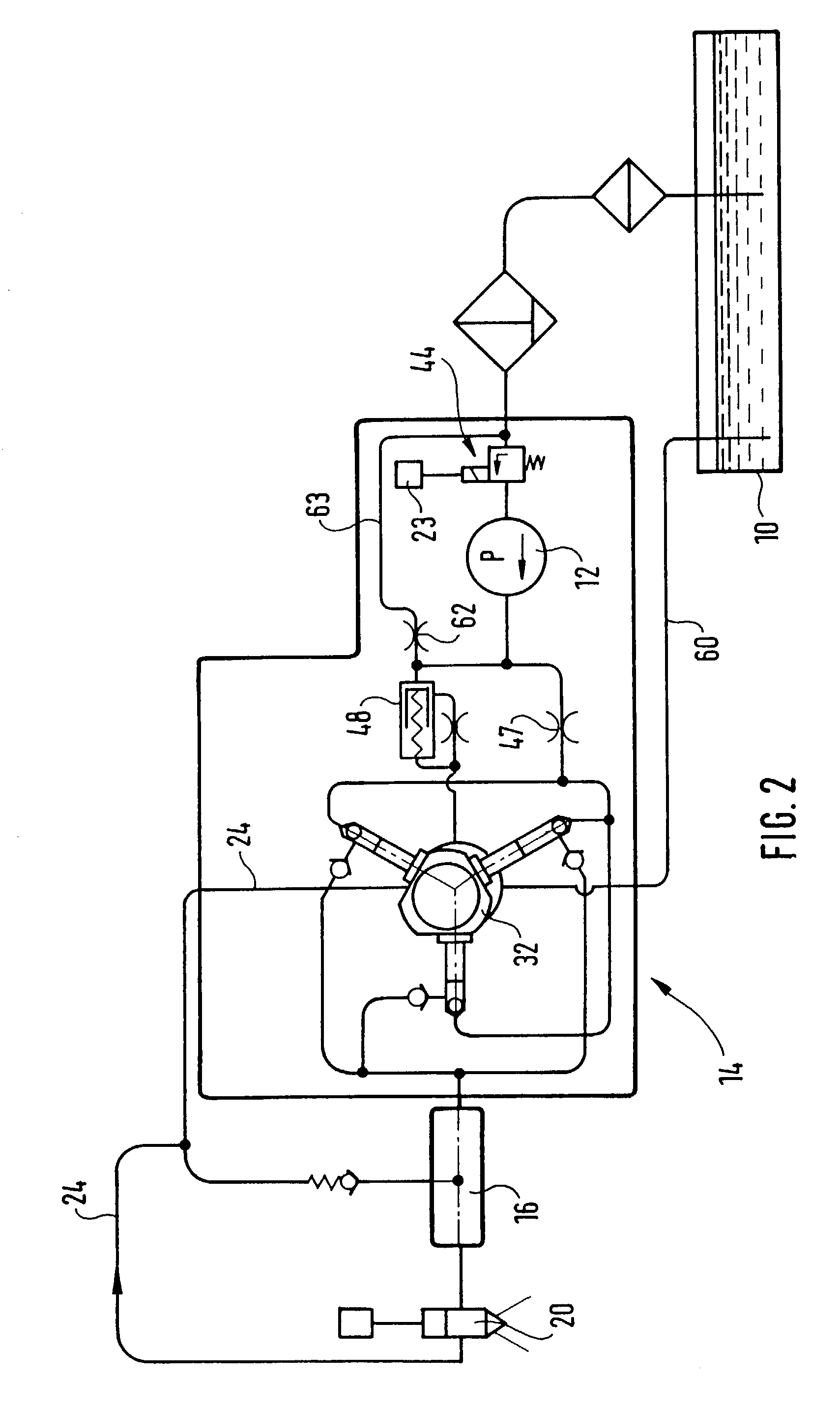
[0013] FIGS. 1-4 show a fuel injection system for an internal combustion engine, for instance in a motor vehicle. The engine is preferably a self-igniting engine and has one or more cylinders. The motor vehicle has a fuel tank 10, in which fuel is kept on hand for operating the engine. The fuel injection system has a prefeed pump 12, by which fuel is pumped from the fuel tank to a high-pressure fuel pump 14. The high-pressure fuel pump 14 pumps fuel into a fuel reservoir 16, which may be embodied in tubular form, for instance, or in some arbitrary other shape. From the fuel reservoir 16, lines 18 lead to injectors 20 disposed at the cylinders of the engine. At each of the injectors 20, a respective electric control valve 22 is disposed, by which an opening of the injectors is controlled, in order to bring about, or prevent, an injection of fuel through the respective injector 20. The control valves 22 are triggered by an electronic control unit 23, by which the instant and duration ...


PUM


Abstract

A fuel injection system having a fuel reservoir, a high-pressure fuel pump by which fuel is pumped into the fuel reservoir as a function of engine operating parameters, a prefeed pump by which fuel is pumped from a fuel tank to the intake side of the high-pressure fuel pump, a fuel metering device for adjusting the fuel quantity pumped into the fuel reservoir by the high-pressure fuel pump, and at least one injector, communicating with the fuel reservoir, for fuel injection to the engine. The metering device is disposed between the fuel tank and the intake side of the prefeed pump. The high-pressure fuel pump has a drive region, which for the sake of its lubrication can be made to communicate with the outlet of the prefeed pump, via a pressure valve that opens towards the drive region.

Description

[0001] 1. Field of the Invention[0002] The invention is directed to an improved fuel injection system for an internal combustion engine.[0003] 2. Description of the Prior Art[0004] One fuel injection system known from German Patent Disclosure DE 198 53 103 A1 has a fuel reservoir and a high-pressure fuel pump, by which fuel is pumped into the fuel reservoir as a function of engine operating parameters. A prefeed pump is also provided, by which fuel is pumped out of a fuel tank to the intake side of the high-pressure fuel pump. A fuel metering device is also provided, for controlling the fuel quantity pumped into the fuel reservoir by the high-pressure fuel pump. The fuel metering device is disposed between the prefeed pump and the high-pressure fuel pump, so that by it, the fuel quantity pumped by the prefeed pump and delivered to the intake side of the high-pressure fuel pump is adjusted. Excess fuel quantity pumped by the prefeed pump is returned to the intake side of the prefeed ...

Claims


Application Information

Patent Timeline
Patent Type & Authority Applications(United States)
IPC IPC(8): F02M37/00F02D41/32F02M59/34F02M63/02F04B23/04F04B49/22
CPCF04B49/225F04B23/04
Inventor SCHMIDL, MATTHIASLETTNER, THOMASREITSAM, ROBERT
Owner ROBERT BOSCH GMBH
Why Eureka
Try Eureka