Current source power conversion circuit

A power conversion and current-type technology, which is applied in the direction of converting AC power input to DC power output, electrical components, and output power conversion devices, can solve problems such as expensive structures and complex current-type power conversion circuits, and achieve space saving. Effect of simplified circuit structure and reduced loss

Inactive Publication Date: 2011-11-16
DAIKIN IND LTD
View PDF6 Cites 4 Cited by
  • Summary
  • Abstract
  • Description
  • Claims
  • Application Information

AI Technical Summary

Problems solved by technology

When a driving power supply is provided for each switching circuit, if it is a 3-phase current-source power conversion circuit, six drive power supplies are required, and there is a problem of becoming an expensive and complicated current-source power conversion circuit

Method used


Image

  • Current source power conversion circuit
  • Current source power conversion circuit
  • Current source power conversion circuit

Examples


Embodiment approach 1

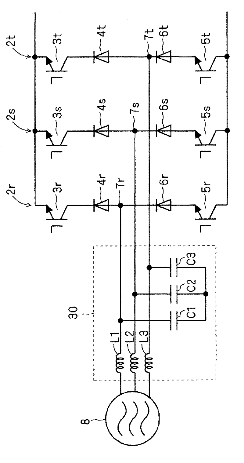
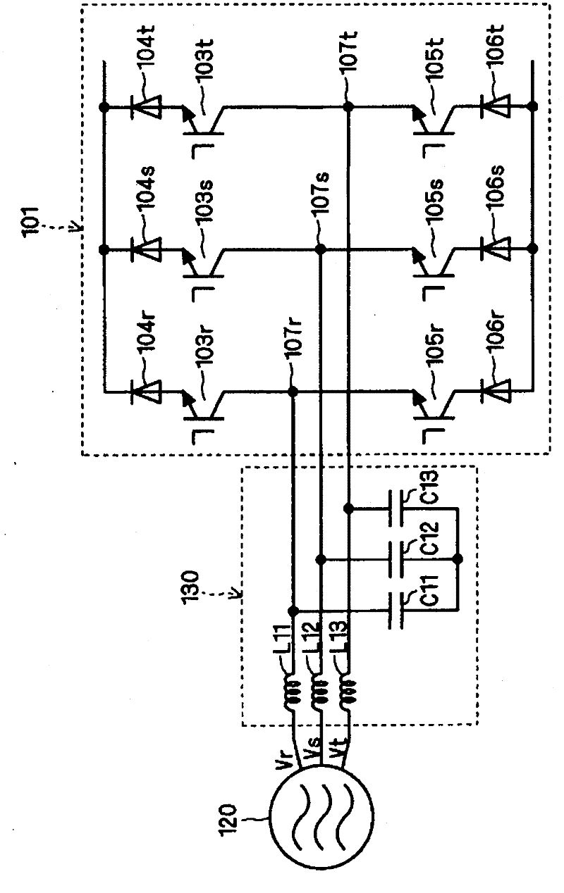
[0041] figure 1 A part of the circuit diagram of the current-source power conversion circuit of the present embodiment is shown. and, figure 2 A circuit diagram of a conventional current-source power conversion circuit is shown.

[0042] first, figure 2 The circuit shown is a 3-phase current-mode rectifier circuit. exist figure 2 In the figure, the 3-phase current source rectification circuit 101, the 3-phase AC power supply 120, and the LC filter circuit 130 are shown in figure. figure 2 The shown 3-phase current-mode rectifier circuit has 3 half-bridge rectifier circuits connected in parallel with each other. Specifically, the half-bridge rectifier circuit corresponding to r has IGBTs 103r and 105r and diodes 104r and 106r. Also, the half-bridge rectifier circuit corresponding to s has IGBT103s, 105s and diodes 104s, 106s. Also, the half-bridge rectifier circuit corresponding to t has IGBTs 103t and 105t and diodes 104t and 106t. IGBTs 103r, 103s, 103t, 105r, 105...

Embodiment approach 2

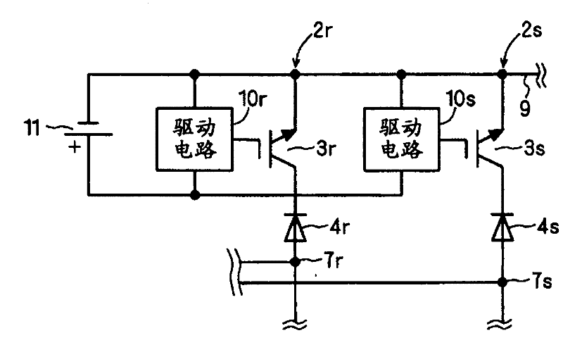
[0051] Figure 4 A circuit diagram of the current-source power conversion circuit of the present embodiment is shown. Figure 4 The current-source power conversion circuit shown is a 3-phase current-source rectifier circuit, however, in Figure 4 In , only IGBT 3r and 3s of two phases (r, s) are described in the upper arm, and IGBT 5r of only one phase (r) is described in the lower arm. exist Figure 4 In the current-source rectifier circuit shown, the emitters of the IGBTs 3r and 3s of each phase are connected to the connection line 9, and the emitters of the IGBTs 3r and 3s function at the same potential, and the IGBTs 3r and 3s of each phase are shared. 3s to drive the drive circuit 10r, 10s drive power supply 11. As described above, the drive power supply 11 can also be shared by the drive circuits that drive the IGBT 3t.

[0052] exist Figure 4 A bootstrap circuit is used in the lower arm of the shown current source rectifier circuit, whereby the driving circuit 13 ...

Embodiment approach 3

[0064] Figure 6 A circuit diagram of the current-source power conversion circuit of the present embodiment is shown. Figure 6 The current-mode power conversion circuit shown is a 3-phase current-mode rectifier circuit. Figure 5 The structure of the 3-phase current-mode rectifier circuit shown is the same as Figure 4 The shown three-phase current source rectifier circuit has substantially the same structure, but the difference is that the diode 12 is not included. The diode 12 is a discharge preventing diode for preventing the capacitor 14 from discharging the power supply 11 . In the three-phase current source rectifier circuit of the present embodiment, the function of the diode 12 is replaced by the diode 4r connected in series with the IGBT 3r. However, the diode 4r needs to have the withstand voltage characteristic required for the diode 12. In a voltage-type inverter, a rectifier circuit, or a current-type inverter, a drive power supply is generally provided with ...


PUM


Abstract

A current source power conversion circuit uses a reduced number of driving power supplies and has an inexpensive and simple configuration. The current source power conversion circuit is provided with a plurality of half-bridge rectifier circuits (2r, 2s, 2t) which are connected in parallel, each comprising a first switch circuit comprising a first self-arc-extinguishing element (3r, 3s, 3t) and a first diode (4r, 4s, 4t) which are connected in series with each other, and a second switch circuit comprising a second self-arc-extinguishing element (5r, 5s, 5t) and a second diode (6r, 6s, 6t) which are connected in series with each other, the first switch circuit and the second switch circuit being connected in series. A first current electrode of the first self-arc-extinguishing element (3r, 3s, 3t) of one half-bridge rectifier circuit (2r, 2s, 2t) and a first current electrode of the first self-arc-extinguishing element (3r, 3s, 3t) of the other half-bridge rectifier circuit (2r, 2s, 2t) are short-circuited and connected.

Description

technical field [0001] The present invention relates to an invention of a current-mode power conversion circuit. Background technique [0002] Generally, a current-source power conversion circuit needs to use an element having a structure preventing reverse conduction in a switching circuit. For example, in a switching circuit, a structure in which an IGBT (Insulated Gate Bipolar Transistor, insulated gate bipolar transistor) and a diode are connected in series is considered. Such a structure is disclosed in Patent Document 1, for example. In addition, in a current-source power conversion circuit employing such a switching circuit composed of IGBTs and diodes, there is known a configuration in which circuits that ensure the reverse withstand voltage of IGBTs are combined in multiple phases. [0003] Furthermore, the current-mode power conversion circuit is used as a current-mode PWM (Pulse Width Modulation, pulse width modulation) rectification circuit. Specifically, it i...

Claims


Application Information

Patent Timeline
Patent Type & Authority Applications(China)
IPC IPC(8): H02M7/5387
CPCH02M7/1623H02M1/08
Inventor 佐藤俊彰
Owner DAIKIN IND LTD
Why Eureka
Try Eureka