Oscillating motor and electric clippers

a technology of oscillating motor and electric clipper, which is applied in the field of motors, can solve the problems of abnormally large operating current, large operating current, and torque too small to produce operating torque, and achieves the effects of reducing driving power, reducing torque, and increasing magnetic flux

Active Publication Date: 2018-12-20
HU JIANKUN
View PDF6 Cites 5 Cited by
  • Summary
  • Abstract
  • Description
  • Claims
  • Application Information

AI Technical Summary

Benefits of technology

[0026]The oscillating motor provided by the present application includes a U-shaped magnetic yoke, four permanent magnets and a swing arm. The two support legs of the U-shaped magnetic yoke are respectively wound with coils, and the end faces of the two support legs can produce alternating magnetic poles with the control circuit. The swing arm can revolve around the fulcrum, and one end thereof near the U-shaped magnetic yoke as an inner arm, and the other end away from the U-shaped magnetic yoke as an outer arm. The four permanent magnets are fixedly mounted on the inner arm via the second magnetic yoke. The four permanent magnets are the first permanent magnet, the second permanent magnet, the third permanent magnet, and the fourth permanent magnet respectively, which are sequentially distributed on the same circumference centered on the fulcrum. The radial end faces of the first and the fourth permanent magnet have the same polarity, the radial end faces of the second and the third permanent magnet have the same polarity, the radial end faces of the first and the second permanent magnet have opposite polarities and correspond to the end face of the first support leg; the radial end faces of the third and the fourth permanent magnet have opposite polarities and correspond to the end face of the second support leg, and there is an air gap between the permanent magnets and the U-shaped magnetic yoke. When a coil is electrified, the four permanent magnets produce torque in the same direction of rotation. After electrified, if the first and third permanent magnets produce the same magnitude of magnetic attraction force to the U-shaped magnetic yoke, the second and fourth permanent magnets produce the same magnitude of magnetic repulsive force to the U-shaped magnetic yoke; if inversely electrified, the first and third permanent magnets produce the same magnitude of magnetic repulsive force to the U-shaped magnetic yoke, then the second and fourth permanent magnets produce the same magnetic of magnetic attraction force to the U-shaped magnetic yoke. Each support leg of the U-shaped magnetic yoke corresponds to two permanent magnets, and such, redundant design for permanent magnet is different from prior art in magnetic circuit design. And it has a larger torque than existing motors of the same power, a larger magnetic flux and a correspondingly reduced driving power. Mechanical units that need to reciprocate within a small moving distance, can be driven directly by such motors without a cam mechanism or an eccentric link structure, but with low noise and stable current And it doesn't need such large current as for a rotating motor to get started and the current changes just in a small way when stalls, and its frequency of swinging does not vary with the resistance. The motor can be powered by a rechargeable battery, which is convenient for a portable design.
[0027]The electric clippers provided by the present application adopt the above-mentioned oscillating motor, and only need a low-voltage direct current (such as 3.7V). The operating current is about 500 mA, the power is about 2 watts, the current during stalling is about 700 mA, the driving current is stable and the swing frequency does not vary with the resistance. With a lower operating current than that of a brushed DC motor, it is more energy-efficient. It can be charged by lithium battery, and there is no large current when starting and stalling, and the battery life is longer, So this design is energy-saving and environment-friendly.

Problems solved by technology

However, when reciprocating oscillating motion is outputted in such a manner that the rotating motor cooperates with the cam mechanism or the eccentric link structure, the operating current is huge, especially when starting and stalling, the operating current is abnormally large.
If such structure is driven by a rechargeable battery at a low voltage, the torque is too small to produce the operating torque, that is, the electric clippers cannot be designed to be wireless and portable.

Method used


Image

  • Oscillating motor and electric clippers
  • Oscillating motor and electric clippers
  • Oscillating motor and electric clippers

Examples


embodiment 1

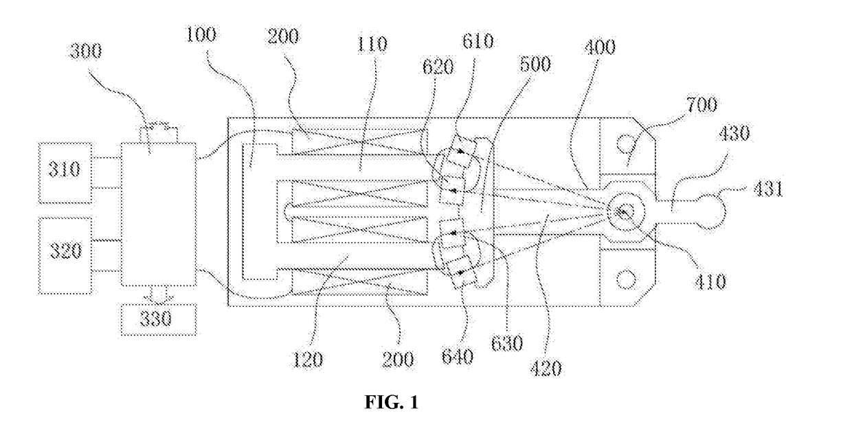
[0040]The first embodiment provides an oscillating motor that can output a reciprocating oscillating motion.

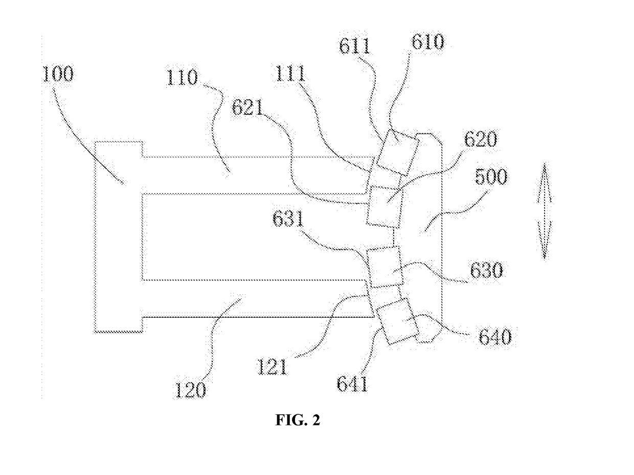
[0041]Referring to FIGS. 1 and 2, the oscillating motor includes:

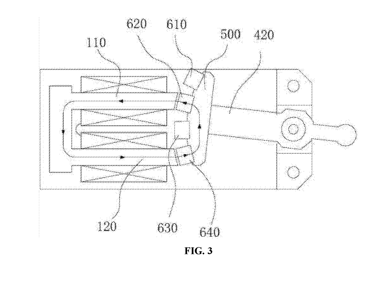
[0042]a U-shaped magnetic yoke 100 with a first support leg 110 and a second support leg 120, wherein the first support leg 110 and the second support leg 120 are respectively wound with coils 200;

[0043]a control circuit 300, which is electrically connected to the coils 200, and produces alternating pulses, so that end faces 111, 121 of the two support legs of the U-shaped magnetic yoke 100 produce alternating magnetic poles;

[0044]a swing arm 400 spinning around a fulcrum extends outward from the end faces 111, 121 of the U-shaped magnetic yoke 100 and bounded by the fulcrum, one end of the swing arm 400 near the U-shaped magnetic yoke 100 as an inner arm 420, the other end of the swing arm 400 away from the U-shaped magnetic yoke 100 as an outer arm 430;

[0045]a second magnetic yoke 500 (which is referred to as a...

embodiment 2

[0069]The second embodiment provides another oscillating motor.

[0070]Referring to FIG. 9, the oscillating motor is improved on the basis of the structure shown in the first embodiment.

[0071]Specifically, an elastic body 810 is provided on both sides of the swing arm to absorb the moment of inertia of the swing arm 400 in the swing position, and the elastic characteristic of the elastic body 810 is a curve of two or more times.

[0072]Wherein, the elastic body 810 is mainly used to absorb the moment of inertia of the swing arm 400 under no-load condition, and the elastic force thereof increases with the compression stroke. Before the position is reached, the elastic force is small, and it rapidly increases when approaching the position. The elastic characteristic of the elastic body 810 can ensure that it does not exert excessive influence on the swing of the swing arm 400 under load (the swinging distance of the swing arm 400 is attenuated under load), and produces a large restoring f...

embodiment 3

[0079]The third embodiment provides another oscillating motor.

[0080]Referring to FIG. 10, the oscillating motor is improved on the basis of the structure shown in Embodiment 1, and a resonant elastic member for producing resonance at a constant swing frequency is added.

[0081]Specifically, the resonant elastic member is fixed at one end on the fulcrum of the swing arm and is connected to the other end to the outer arm or the inner arm.

[0082]Further, the resonant elastic member shown in FIG. 10 is a linear spring steel wire. Further, other shapes of elastic members may be used instead, for example, the central portion of the resonant elastic member as shown in FIG. 10 is curved.


PUM


Abstract

Provided is an oscillating motor and electric clippers. The oscillating motor includes a U-shaped magnetic yoke, four permanent magnets and a swing arm. The U-shaped magnetic yoke causes end faces of two support legs to produce alternating magnetic poles with the control circuit. The four permanent magnets are fixedly mounted to an inner arm via a second magnetic yoke. The four permanent magnets are sequentially distributed on a same circumferential surface having a fulcrum being a circle centre. The polarities of radial end faces of the first permanent magnet and the fourth permanent magnet are the same. The polarities of radial end faces of the second permanent magnet and the third permanent magnet are the same, and the opposite of the polarity of the radial end face of the first permanent magnet. When a coil is electrified, the four permanent magnets produce torque having the same direction of rotation.

Description

TECHNICAL FIELD[0001]The present invention relates to a motor, and more specifically, to a motor that outputs an oscillating motion.BACKGROUND[0002]A motor is an electromagnetic device that converts electric energy based on the law of electromagnetic induction. It is widely used in various fields and as an indispensable prime mover in today's society, it provides a motive power source for a large number of electric appliances or machines.[0003]Electric clippers are a kind of equipment powered by motors At present, motors for electric clippers include rotating motors and oscillating motors. A rotating motor is a rotating electromagnetic machine that operates on the principle of electromagnetic induction to realize mutual conversion between to mechanical energy and electric energy. Meanwhile, the rotating motor converts rotary motion into reciprocating oscillating motion by means of a transmission mechanism. A typical transmission mechanism is for example a cam mechanism or an eccentr...

Claims


Application Information

Patent Timeline
Patent Type & Authority Applications(United States)
IPC IPC(8): B26B19/28B26B19/12
CPCH02K33/16B26B19/12B26B19/28H02K33/18B26B19/284
Inventor HU, JIANKUNHU, JIANCHANGHU, FEIRANHU, FEIFAN
Owner HU JIANKUN
Why Eureka
Try Eureka