Recording target medium and recording apparatus

a target medium and recording target technology, applied in the field of recording target medium and recording apparatus, can solve the problems of affecting the quality of the recorded image, affecting the degree of white and affecting the accuracy so as to enhance the degree of whiteness, the sense and/or degree of whiteness of the recording target medium and the effect of enhanced positional precision

Active Publication Date: 2010-07-01
SEIKO EPSON CORP
View PDF1 Cites 5 Cited by
  • Summary
  • Abstract
  • Description
  • Claims
  • Application Information

AI Technical Summary

Benefits of technology

[0009]Application Example 1 (First Aspect): A recording target medium includes a base material, a recording portion that is formed on or at one surface of the base material, and a guided-array portion that is formed on the base material at a side opposite to an observation side of the recording portion. The recording portion includes an ink-accepting layer. Having the above structure, a recording target medium according to the first aspect of the invention is transported along its guided-array portion. Therefore, the transportation direction of the recording target medium is accurately controlled in a fixed direction. For this reason, positional precision in the recording of an image or the like on the recording target medium may be enhanced.
[0010]Application Example 2: In the structure of the recording target medium according to the first aspect of the invention, it is preferable that the guided-array portion have the shape of an array of convex semi-cylinders, concave semi-cylinders, triangles, convexes, or concaves. Since the recording target medium can include one of the above shapes, the guided state may be maintained with greater reliability.
[0011]Application Example 3: In the preferred structure of the recording target medium described above, the guided-array portion can be colored. For example, if the color of the guided-array portion is white, the sense and / or degree of whiteness of the recording target medium and its glossiness may be enhanced.
[0012]Application Example 4 (Second Aspect): A recording apparatus for performing recording on a recording target medium includes a supporting section that supports the recording target medium; and a guiding-array portion that is formed on the supporting section. The guiding-array portion guides the guided-array portion of a recording target medium according to the first aspect. Having the above configuration, the recording apparatus according to the second aspect of the invention makes it possible to accurately control the transportation direction of a recording target medium in a fixed direction. For this reason, positional precision in the recording of an image or the like on the recording target medium may be enhanced.
[0013]Application Example 5: It is preferable that a recording apparatus according to the second aspect of the invention further include a pressing section that presses the recording target medium against the guiding-array portion. Since the recording apparatus preferably has the above configuration, the pressing section ensures engagement between the guided-array portion and the guiding-array portion (e.g., lenticular engagement). Therefore, the transportation direction of the recording target medium is accurately controlled in a fixed direction with greater reliability. For this reason, positional precision in the recording of an image or the like on the recording target medium may be further enhanced.
[0014]Application Example 6: In the configuration of a recording apparatus having the preferred configuration, the pressing section can be a roller that rotates in a rotation direction that agrees with a direction of transportation of the recording target medium. With such a configuration, since the roller rotates toward the transportation direction of the recording target medium, it is possible to reduce driving power that is required for transporting the recording target medium.

Problems solved by technology

If a recording target medium meanders or inclines during transportation, the quality of the recorded image may be degraded.
An extra-fine ruled line may be distorted due to discontinuity and / or poor linearity.
It is difficult to exactly position the guide members to align both edges of a recording target medium whose shape is susceptible to change without leaving a gap between the guide members and the recording target medium.
For example, it is difficult to align the guide members with plain paper or photo paper, either of which change shape easily, with perfect positional precision.
The same difficulty exists in trying to align a recording target medium with rough and / or uneven edges.

Method used


Image

  • Recording target medium and recording apparatus
  • Recording target medium and recording apparatus
  • Recording target medium and recording apparatus

Examples


Embodiment Construction

[0024]In the following description, various embodiments of the present invention will be described. For purposes of description, specific configurations and details are set forth in order to provide a thorough understanding of the embodiments. However, it will also be apparent to one skilled in the art that the present invention may be practiced without the specific details. Furthermore, well-known features may be omitted, or simplified in order not to obscure the embodiment being described.

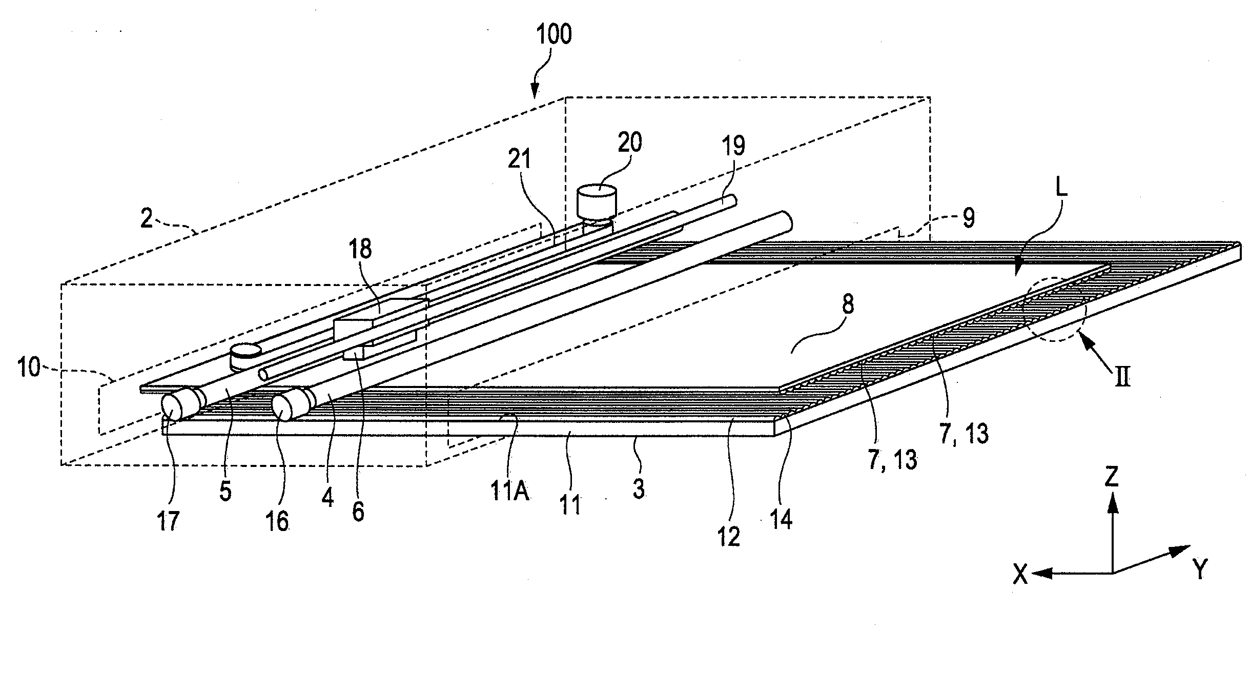
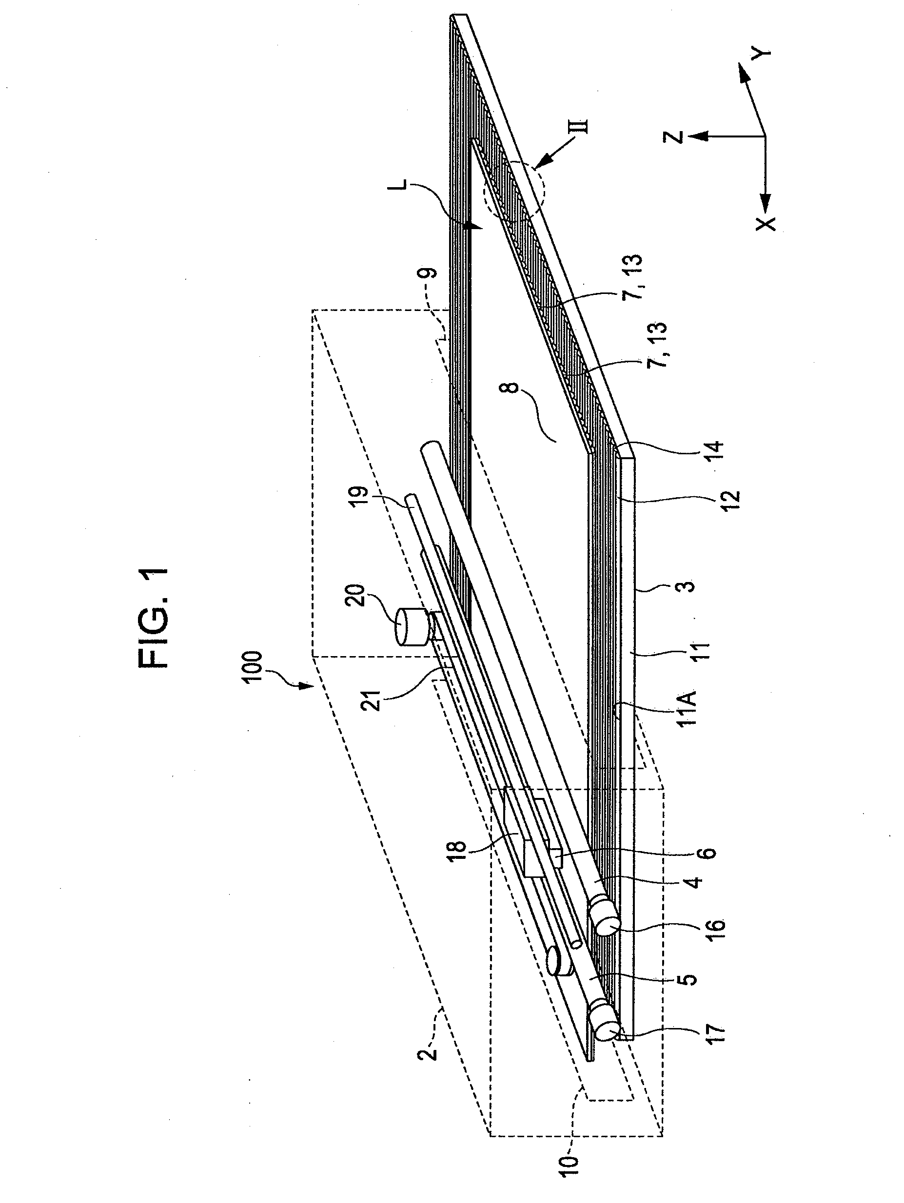
[0025]Referring now to the drawings, in which like reference numerals represent like parts throughout the several views, FIGS. 1, 2, and 3 show a recording target medium (L) and a recording apparatus 100, in accordance with the embodiments of the present invention.

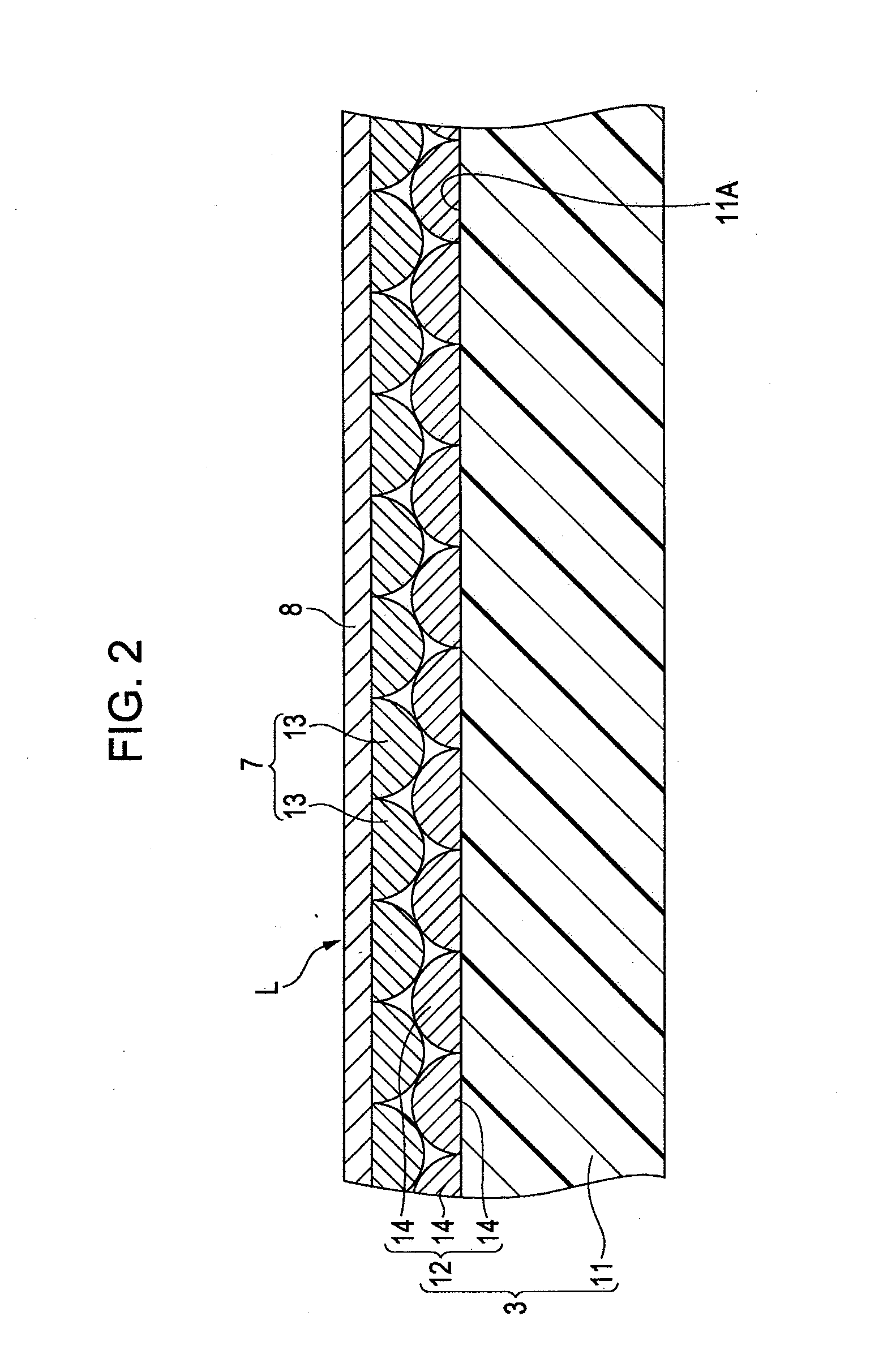
[0026]FIG. 1 is a rear-perspective view that schematically illustrates the recording apparatus 100 on which the recording target medium (L) is placed. FIG. 2 is an enlarged cross-sectional view of area II of FIG. 1 illustrating engageme...


PUM

PropertyMeasurementUnit
thicknessaaaaaaaaaa
thicknessaaaaaaaaaa
incremental angleaaaaaaaaaa

Abstract

A recording target medium includes a base material, a recording portion, and a guided-array portion. The recording portion is formed on or at one surface of the base material. The recording portion includes an ink-accepting layer. The guided-array portion is formed on the base material at a side opposite to an observation side of the recording portion.

Description

CROSS-REFERENCES TO RELATED APPLICATIONS[0001]Priority is claimed under 35 U.S.C. §119 to Japanese Application No. 2008-332958 filed on Dec. 26, 2008 which is hereby incorporated by reference in its entirety.BACKGROUND[0002]1. Technical Field[0003]The present invention generally relates to a recording apparatus such as an ink-jet printer and to a recording target medium. In particular, the invention relates to a technique for improving positional precision in recording on a recording target medium.[0004]2. Related Art[0005]Many existing recording apparatuses, such as many printers, transport a recording target medium during the recording process. If a recording target medium meanders or inclines during transportation, the quality of the recorded image may be degraded. For example, printed letters in small font may be blurred. An extra-fine ruled line may be distorted due to discontinuity and / or poor linearity. To avoid such quality degradations, high positional precision is desirabl...

Claims


Application Information

Patent Timeline
Patent Type & Authority Applications(United States)
IPC IPC(8): B41J29/393B41M5/50
CPCB41J11/06B41M5/508
Inventor SUZUKI, KATSUHITO
Owner SEIKO EPSON CORP
Why Eureka
Try Eureka