Welding or joining unit

a technology of joining unit and welding head, which is applied in the direction of resistance welding apparatus, resistance electrode holders, arc welding apparatus, etc., and can solve problems such as increasing programming effor

Inactive Publication Date: 2004-01-29
H A SCHLATTER A G
View PDF5 Cites 15 Cited by
  • Summary
  • Abstract
  • Description
  • Claims
  • Application Information

AI Technical Summary

Benefits of technology

[0010] By the arrangement of the at least two tools on a rotatable turret unit, the programming becomes very much simpler. Since the production of the connection relative to the supporting construction of the welding or joining unit is always effected at the same location, optimum internal stability is also obtained. The desired tool is brought into position by rotating the turret unit. Thus the construction of the welding or joining unit having a plurality of tools becomes simpler and the possibility of collisions between the tools and the spatially configured workpieces during the positioning of the latter is reduced, for example compared with a welding machine having a plurality of welding tools arranged side by side. In this context, spatially configured or nonplanar workpieces essentially refer to any type of grid (e.g. baskets, oven grids, special grids, etc.) and three-dimensional metal sheets, for the most varied applications, which may have any desired spatial form.
[0031] A plurality of identical electrodes on a turret may also possibly help to ensure that the individual electrode (on account of shorter use) is heated to a less pronounced extent. By the time the electrode originally used comes into use again, it has cooled down, as a result of the cooling carried out, to such an extent that it can be used again for further welds, which leads to a longer service life.

Problems solved by technology

Furthermore, during the positioning of the plurality of welding tools arranged side by side, and due to the spatial configuration of the workpieces, collisions may occur, which are to be taken into account when programming the welding machine and which additionally increase the programming effort.

Method used


Image

  • Welding or joining unit
  • Welding or joining unit
  • Welding or joining unit

Examples


Embodiment Construction

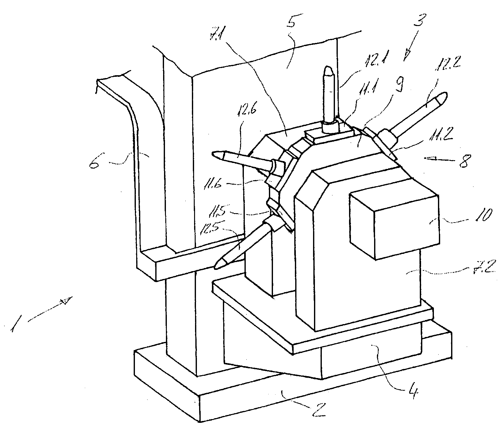
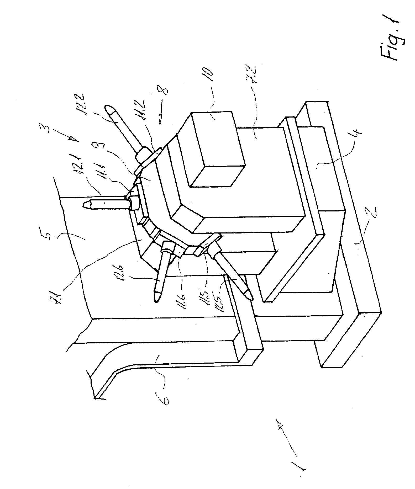
[0008] The object of the invention is to provide a welding or joining machine in which a plurality of tools are arranged on a welding or joining machine and, compared with the known solutions, even in the case of workpieces of complex spatial form, the time needed to avoid collisions is short and the programming effort is small.

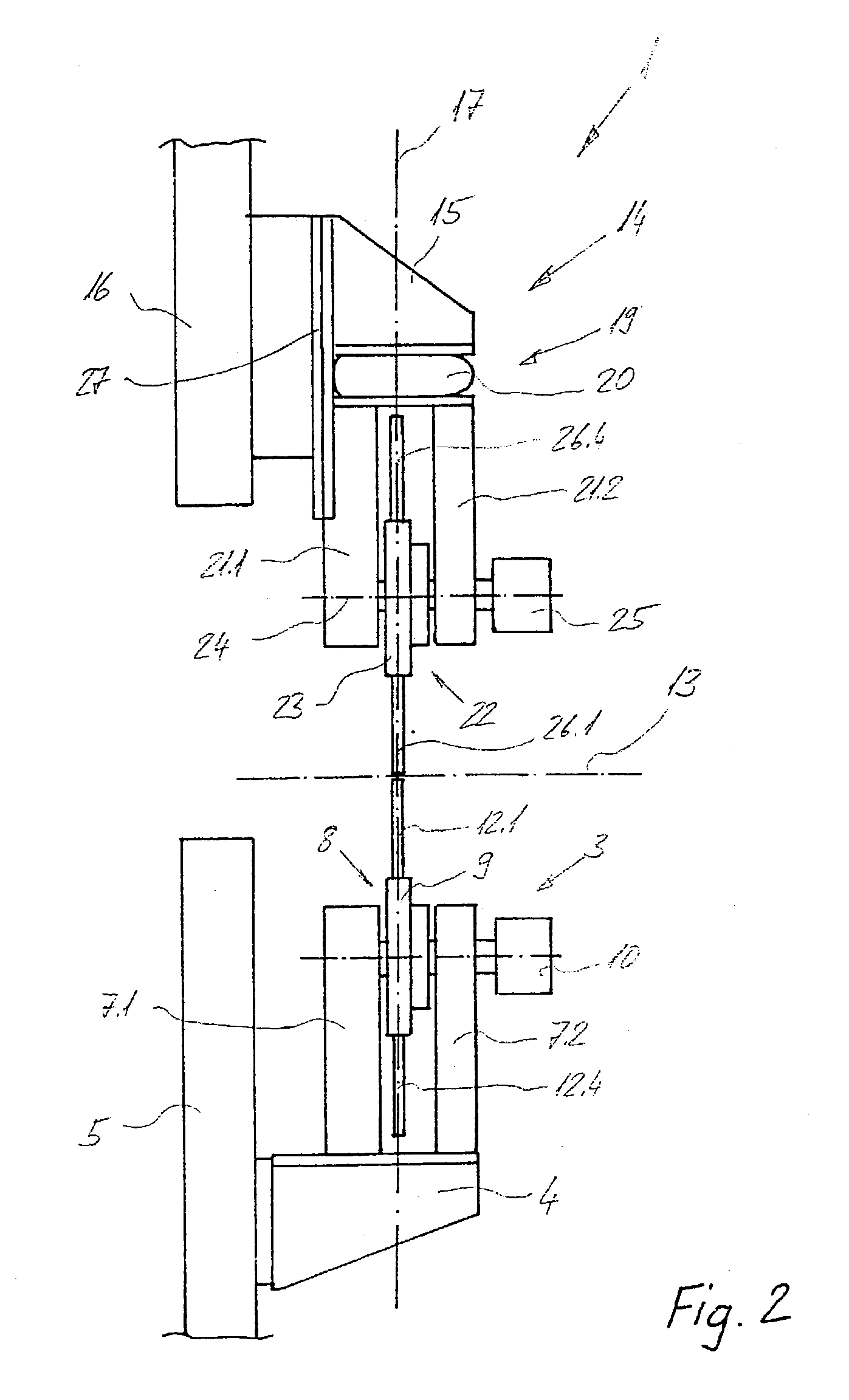
[0009] The solution achieving the object is defined by the features of claim 1. According to the invention, a welding or joining unit is provided, in particular for connecting workpieces having any desired spatial forms, comprising at least two tools, a set-down unit for setting down the tools on the workpiece by open-loop or closed-loop control, and a readjusting unit for readjusting the tools. The at least two tools are arranged on at least one turret unit having a servo axis which can be programmed so as to be optimized with respect to time.

[0010] By the arrangement of the at least two tools on a rotatable turret unit, the programming becomes very much sim...


PUM

PropertyMeasurementUnit
timeaaaaaaaaaa
electricaaaaaaaaaa
pressureaaaaaaaaaa

Abstract

In a welding or joining unit (1), in particular for connecting workpieces having any desired spatial forms, at least two tools (12.1 to 12.[lacuna]) are arranged on a turret unit (3) which has a servo axis which can be programmed so as to be optimized with respect to time. Furthermore, the welding or joining unit (1) has a set-down unit (14) and a readjusting unit (19) and also a tool arranged thereon. By rotation of the turret unit (3), the tool (e.g. 12.1) designed for the desired type of connection is brought into position and the connection is produced.

Description

[0001] The invention relates to a welding or joining unit, in particular for connecting workpieces having any desired spatial forms, comprising at least two tools, a set-down unit for setting down the tools on the workpiece by open-loop or closed-loop control, and a readjusting unit for readjusting the tools.PRIOR ART[0002] Workpieces of sheet metal and / or wire which are joined together from a plurality of parts are used as semifinished or finished products in many fields of application. These workpieces are mostly workpieces having any desired spatial form, in particular a nonplanar configuration. Furthermore, the workpieces are produced from materials which are the same or different but which can be welded to one another or joined together.[0003] Various types of connections are often executed on one and the same workpiece. For example, the individual parts are at least spot-welded to one another or joined together in a spot-like manner, e.g. riveted to one another. In order not t...

Claims


Application Information

Patent Timeline
Patent Type & Authority Applications(United States)
IPC IPC(8): B23K11/31
CPCB23K11/312
Inventor ROHNER, JURG
Owner H A SCHLATTER A G
Why Eureka
Try Eureka