Protection barrier apparatus

Inactive Publication Date: 2004-01-29
ITA INDAL +1
View PDF16 Cites 66 Cited by
  • Summary
  • Abstract
  • Description
  • Claims
  • Application Information

AI Technical Summary

Problems solved by technology

While the use of GRP for components of a harbor protection barrier is an improvement over the use of a mostly-steel or an all-steel construction for a harbor protection barrier in some respects (e.g., lower maintenance costs), it still has problems associated with not being as structurally strong as the mostly-steel construction, and thereby it does not provide as good a protection or durability as one would get from the mostly-steel construction or all-steel construction of a harbor protection barrier.
One can surmise from that test that boats following a lead boat (which impacted the GRP protection barrier) may be able to follow the same path in the water as the lead boat and thereby penetrate into a region protected by one or more GRP protection barriers, which is clearly undesirable.
Furthermore, conventional GRP Port Security barrier modules are not particularly sturdy with respect to dealing with forces due to boat attacks and/or forces due to severe weather conditions.
Also, for an all-steel construction or for a mostly-steel construction of a Port Security barrier, there is a problem in that maintenance costs are very high.
For example, when the Port Security barrier is floating in the water, it deteriorates over time due

Method used


Image

  • Protection barrier apparatus
  • Protection barrier apparatus
  • Protection barrier apparatus

Examples


first embodiment

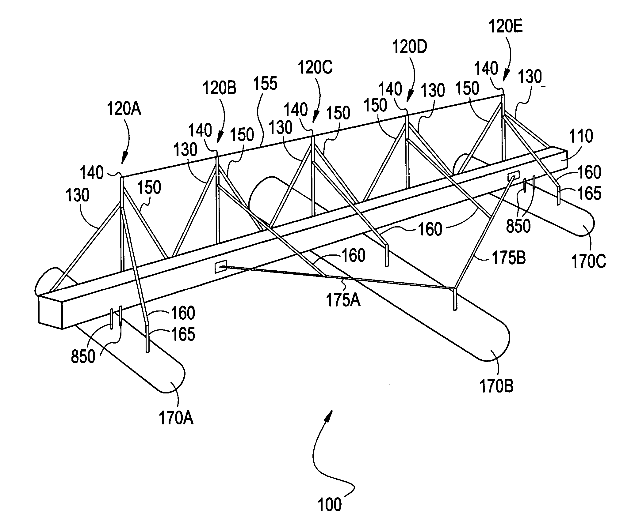
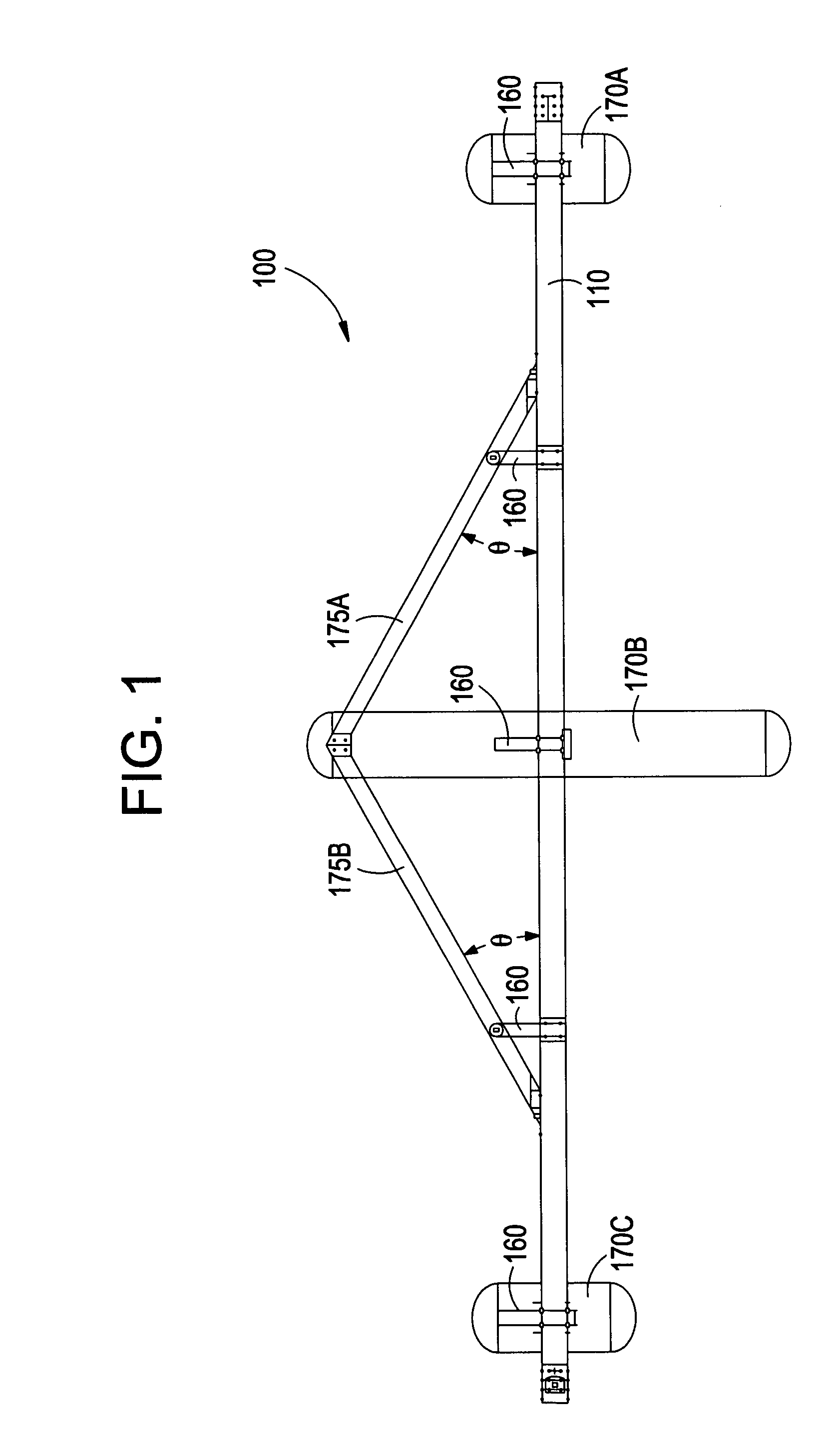
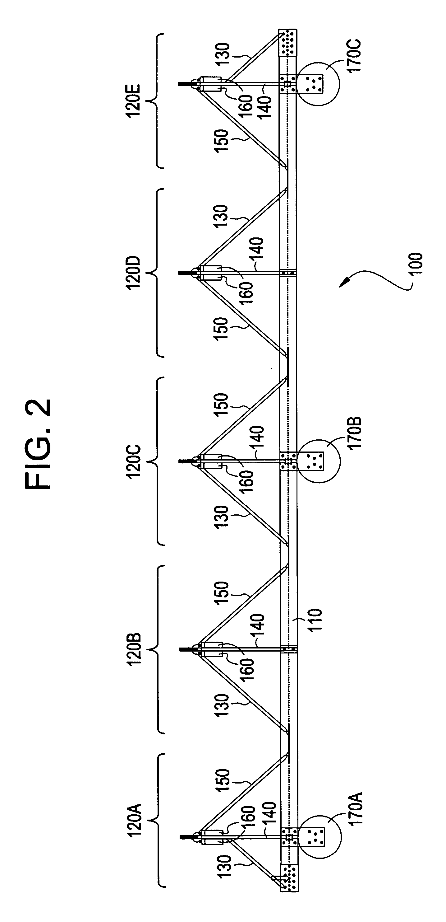
[0034] The HPB according to the invention is made up of individual protection barrier units, such as the one shown in FIG. 1 (top view), FIG. 2 (side view) and in FIG. 3 (top perspective view). The part of the HPB that does not float in the water is made up primarily of composite materials such as pultruded fiberglass reinforced plastics (FRP) that have structural properties that are comparable to steel.

[0035] The HPB system also uses a novel structure to provide buoyancy for the individual protection barrier unit, by way of foam-filled pontoons. Each pontoon is preferably cylindrical in shape (a rectangular construction of the pontoons is possible in an alternative configuration) and is preferably 28 inches in diameter, whereby each pontoon is constructed out of solid urethane (constituting the core of the pontoon) and polyethylene provided around the urethane core (where the polyethylene is preferably obtained in flexible rectangular sheets and then fitted over the urethane core) ...

second embodiment

[0067] The connector 400 operates as a dampener with respect to the two adjacent floating protection barrier modules 100 that it couples together. The connector 400 includes combined tensile and dampening materials working together as a single unit. The tensile material is a chain 110 in a preferred construction, but it could also be a cable, wire, rope, structural steel, or synthetic line.

[0068] In the preferred embodiment, the dampening material includes a rubber hose 420 and molded polyurethane 430, but it could also be a similar natural or synthetic material (e.g., other type of polymer instead of polyurethane with similar properties) configured to: a) carry connector tension during low load conditions, and b) transfer load to the tensile member during high load periods, and / or c) dampen motion from one protection barrier unit to an adjacent protection barrier unit as the protection barrier system is subject to wave motion or other forces. The rubber hose is 420 is preferably c...

fourth embodiment

[0079] As described in some detail earlier, the HPB system according to the present invention uses a novel pontoon structure to provide buoyancy for the individual protection barrier unit, whereby the pontoon structure corresponds to the invention, as shown in FIG. 8. The pontoon 170 is preferably cylindrical in shape (a rectangular construction of the pontoons is utilized in an alternative configuration) and is preferably 28 inches in diameter, whereby each pontoon 170 has a solid urethane core 820 with a portion of a galvanized steel structure 850 also disposed therein. These two components form the inner shell of the pontoon 170. Polyethylene sheets are provided around the inner shell to thereby form a polyethylene ring 840 around the inner shell, whereby each sheet is preferably a rectangular sheet that can be readily obtained commercially. An outer shell of high strength polyurethane elastomer 830 is then formed around the polyethylene ring 840. In a preferred method of constru...


PUM

PropertyMeasurementUnit
Lengthaaaaaaaaaa
Angleaaaaaaaaaa
Lengthaaaaaaaaaa

Abstract

A protection apparatus protects a harbor or an area in a body of water or adjacent to a body of water. The protection apparatus floats on the body of water, and includes a plurality of barrier units positioned side-by-side, each of the barrier units includes a composite-based durable barrier structure. The barrier structure is configured to hold a net in place in order to protect an area in the body of water or abutting the body of water from waterborne craft. The protection apparatus also includes connectors respectively provided between adjacently-positioned ones of the barrier units. Each of the connectors includes a tensile member and a dampening member for handling forces applied to the protection barrier and for maintaining the integrity of the protection barrier.

Description

[0001] This application claims priority from provisional application Serial No. 60 / 400,130, filed on Aug. 2, 2002, entitled "ITA Harbor Protection Barrier", by the same inventors as this application.[0002] A. Field of the Invention[0003] The invention relates generally to protection barriers and, more particularly, to durable, lightweight floating barriers that are used to protect areas such as harbors, water regions, or other types of land or water areas from high speed water craft attack.[0004] B. Description of the Related Art[0005] In the current environment with terrorist activities on the rise, there is a need to protect assets from terrorist attacks. One type of protection device is a floating harbor protection barrier system designed to provide protection to military and commercial harbors from high speech surface boat attacks.[0006] Initial research into harbor protection by the Naval Facilities Engineering Service Center led to the development of a mostly-steel structure c...

Claims


Application Information

Patent Timeline
IPC IPC(8): B63B5/24B63B35/34F41H11/05
CPCB63B5/24F41H11/05B63B2005/245B63B35/34
Inventor KNEZEK, ERICK B.MARCY, MATTHEW A.TRUSTON, ROBERT C.
Owner ITA INDAL
Why Eureka
Try Eureka