
LAN switching method and LAN switch

a switching method and switch technology, applied in the field of local area network switch, can solve the problems of taking a certain time to establish the spanning tree, adversely affecting other traffics, and never completes the series of processing by the stp instantaneously

Inactive Publication Date: 2004-02-19
FUJITSU LTD
View PDF4 Cites 81 Cited by
  • Summary
  • Abstract
  • Description
  • Claims
  • Application Information

AI Technical Summary

Problems solved by technology

When no measures are taken against the loop on the network path, the switches 100a-100c keep transferring frames around the loop, thereby adversely affecting other traffics.
However, it takes a certain time to establish the spanning tree.
However, such a series of processing by the STP is never completed instantaneously.
Also, it is practicably impossible to dynamically or intermittently change the path in the same VLAN.
Thus, an optimum path change and a load distribution can not be realized.
However, the EoMPLS is required to mount thereon a plurality of complicated routing protocols on the basis of MPLS, whereby developments of products realizing the EoMPLS and the system operation are made complicated.
Therefore, it becomes impossible for the user to fully enjoy benefits the Ethernet originally provides.

Method used


Image

  • LAN switching method and LAN switch
  • LAN switching method and LAN switch
  • LAN switching method and LAN switch

Examples


embodiment (

[0283] Embodiment (10): Notification of Line Fault by Alarm Transferring Frame

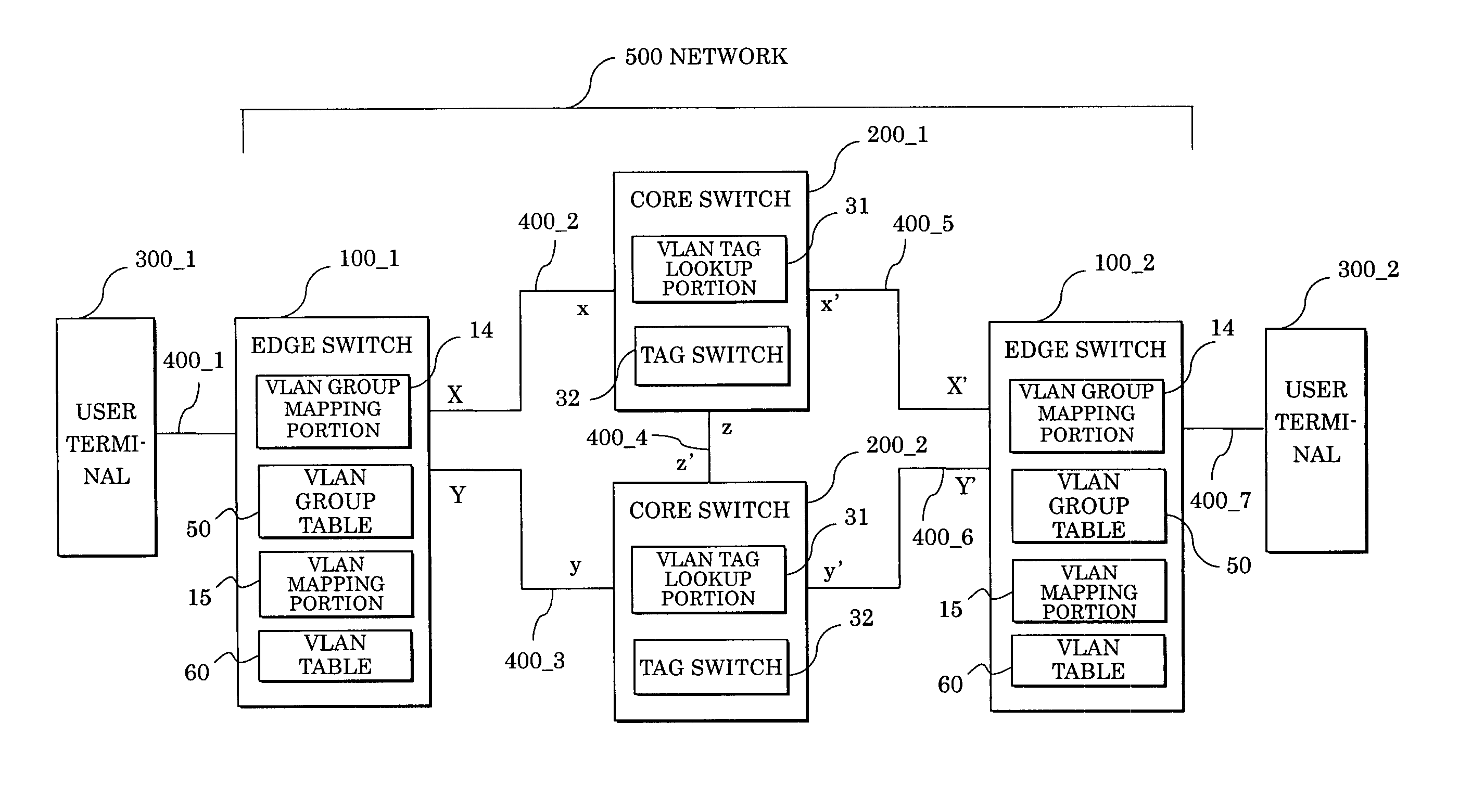
[0284] FIG. 25 shows an embodiment (10) of a LAN switch 100 according to the present invention. This LAN switch 100 is different from that of the embodiment (2) shown in FIG. 7 in that a line fault detector 26 is substituted for the line fault detector 19 and an alarm processor 27 is further provided.

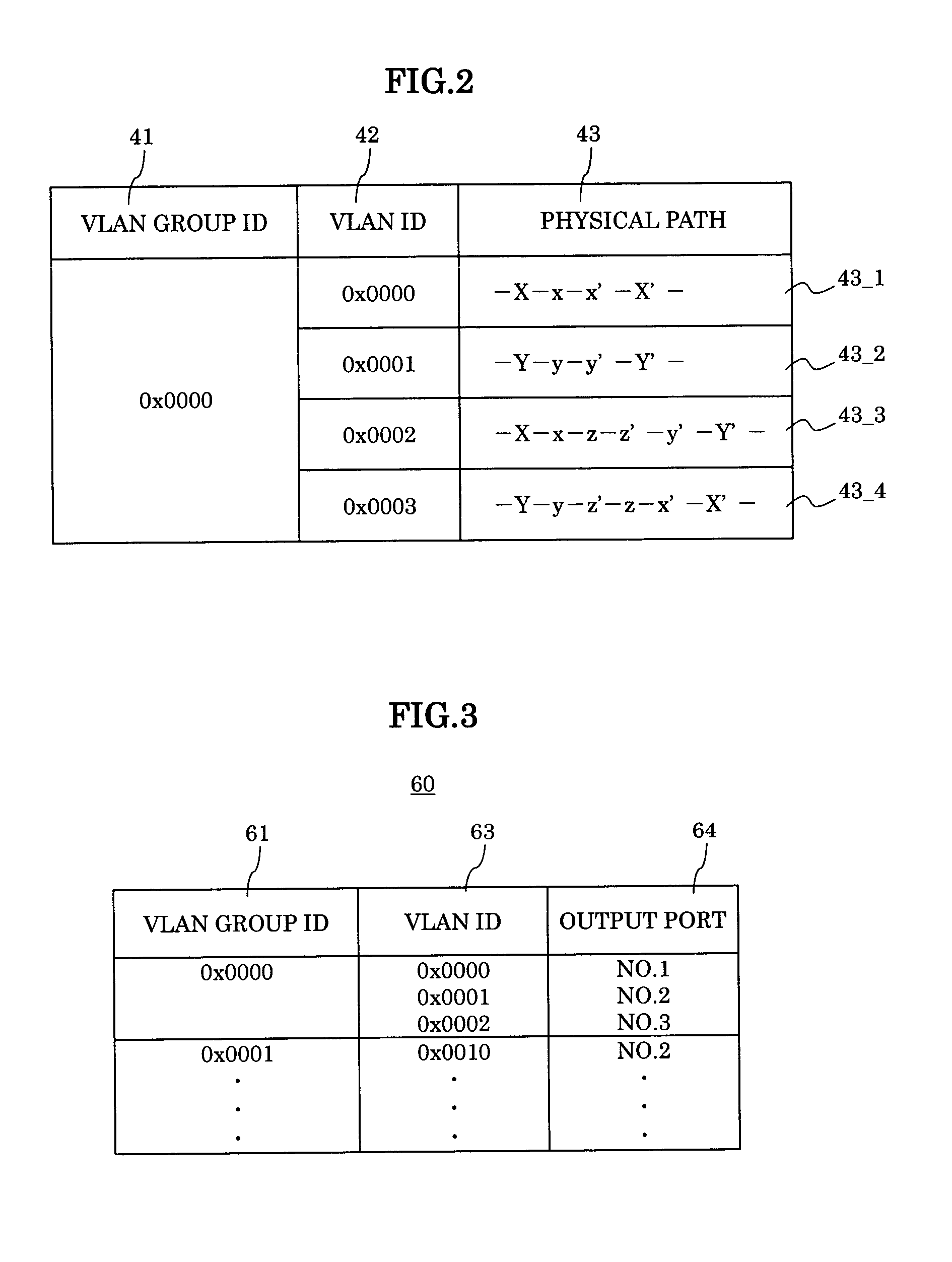
[0285] It is to be noted that the VLAN group table 50a and the VLAN table 60b are respectively the same as those (see FIGS. 8 and 12) of the embodiment (2).

[0286] In operation, when detecting a line fault with control frame information 826 from the frame analyzer 13, the line fault detector 26 sets the link disable 67 associated with the entry of the VLAN using the line in which a fault has occurred, to "1" with a link-disabling set / reset signal 827.

[0287] Furthermore, the line fault detector 26 provides an alarm distribution request 828 including the ID of the concerned VLAN to the alarm processor 27, and req...


PUM


Abstract

In a LAN switch capable of recognizing a VLAN, a plurality of paths are associated with a VLAN having a plurality of same members as components, and frames from the members are mapped to a predetermined path selected from among the paths. Also, a plurality of different VLAN's are associated with a single group composed of a plurality of members, and frames from the members are mapped to a predetermined VLAN selected from among the VLAN's. Furthermore, information of a frame is associated with the group to which a member having transmitted the frame belongs, and the received frame is mapped to the group to which the member having transmitted the frame belongs, based on the information of the frame.

Description

[0001] 1. Field of the Invention[0002] The present invention relates to a LAN (Local Area Network) switch, and in particular to a LAN switch capable of recognizing a Virtual LAN (hereinafter, abbreviated as VLAN).[0003] Recently, together with developments of communication technology, the speed of a LAN has been enhanced so that a LAN with a speed in the order of Gbps has been realized. Also, as a bridge connecting LAN's, a LAN switch of layer 2 has been remarkable and has become widely available. On such a high-speed LAN switch, its service quality has become more and more important.[0004] 2. Description of the Related Art[0005] FIG. 26 shows an example of an Ethernet network 500 defined by IEEE 802.3 using a LAN switch.[0006] The network 500 is composed of a LAN switch 100a to which a user terminal 300a is connected with a link 400a, a LAN switch 100c to which a user terminal 300b is connected with a link 400e, and a LAN switch 10b. The switches 100a, 100b, and 100c are connected ...

Claims


Application Information

Patent Timeline
IPC IPC(8): H04L12/46H04L12/70
CPCH04L12/4641H04L12/4691H04L49/602H04L49/354H04L49/351
Inventor ODA, SOTAROKITADA, ATSUSHI
Owner FUJITSU LTD
Learn More