Relaying system for broadcasting multi-channel internet television and networking method thereof

Inactive Publication Date: 2004-02-26
SUNGJIN C&C
View PDF3 Cites 10 Cited by
  • Summary
  • Abstract
  • Description
  • Claims
  • Application Information

AI Technical Summary

Problems solved by technology

The clustering method illustrated in FIG. 2, however, is not suitable for the live webcasting, which broadcasts the encoded data for moving pictures in real time.
However, it is not practically easy for a content-provides to have a high-performance server as well as a network line with a large bandwidth.
Moreover, in the case of the multi-channel broadcasting system, which broadcasts the real-time traffic conditions of the roads, it is not economical to prepare a great number of high performance live servers on the roads and network with a large bandwidth.
Since each server is responsible for one channel according to the prior art, ea

Method used


Image

  • Relaying system for broadcasting multi-channel internet television and networking method thereof
  • Relaying system for broadcasting multi-channel internet television and networking method thereof
  • Relaying system for broadcasting multi-channel internet television and networking method thereof

Examples


Embodiment Construction

[0033] The present invention will be explained in detail with reference to the accompanying drawings.

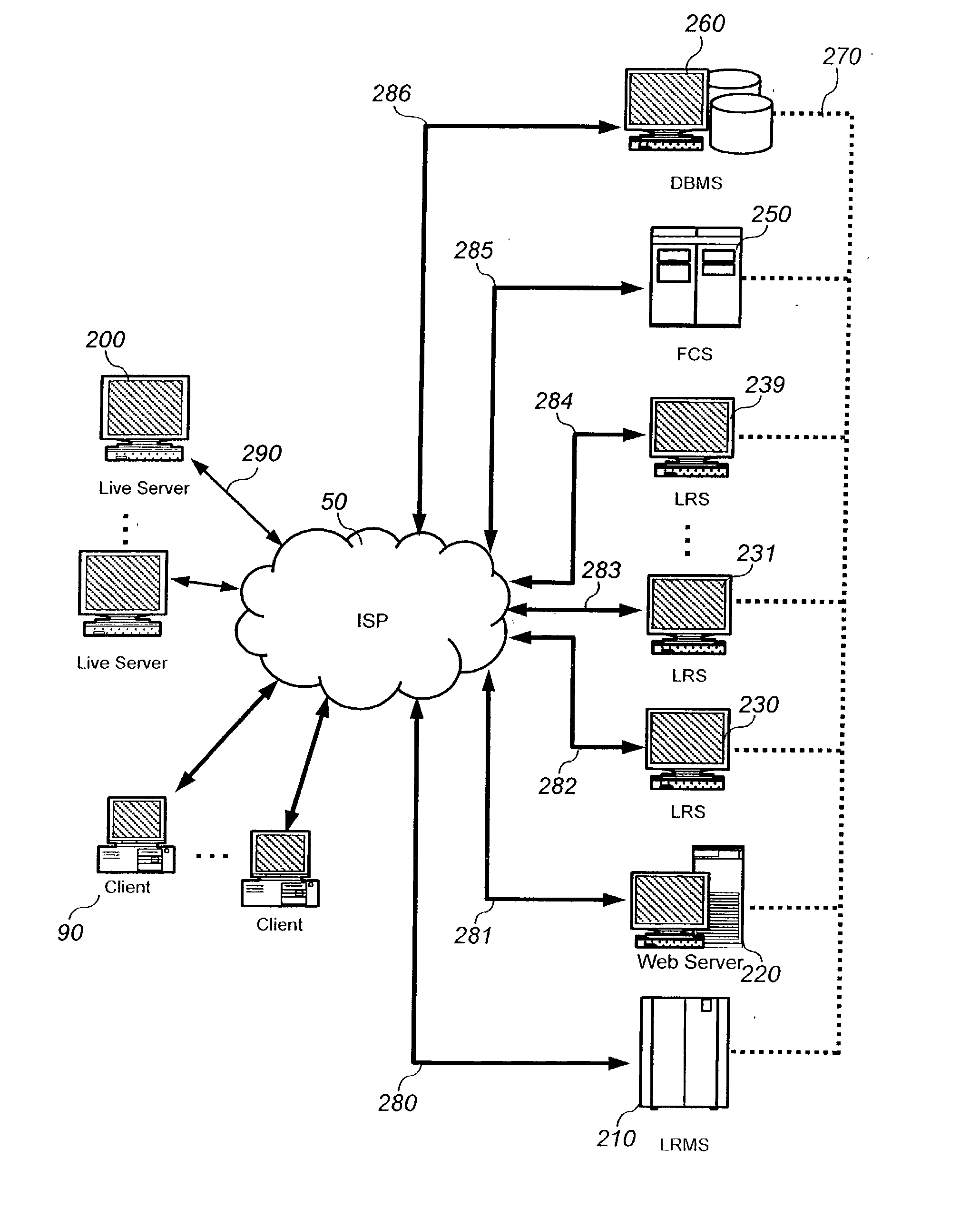
[0034] FIG. 3 is a schematic diagram illustrating a preferred embodiment of a relaying system for Internet television broadcasting in accordance with the present invention.

[0035] Referring to FIG. 3, a multiple of individual live servers 200 provide a real-time live broadcasting service, respectively. Namely, the live server 200 sends a stream of encoded audio and video data for television broadcasting on Internet.

[0036] Since each live server for each channel can not afford to broadcast Internet television program to time-varying number of clients, each local live server sends its data stream to the relaying system in accordance with the present invention. The relaying system is then responsible for broadcasting of multi-channels through the system comprising the live relay management server (LRMS) 210, web server 220, a multiple of relaying servers 230, 231, 239, a frame conversion...


PUM


Abstract

The present invention discloses a relaying system for multi-channel Internet broadcasting from a local live server. The present invention makes it possible to have a multiple of live relaying servers shared by several local servers depending on the number of connections requested by client computers.

Description

[0001] The present invention relates to a relaying system for broadcasting multi-channel internet television and networking method thereof, and more particularly to a multi-media relaying technology which alleviates the burden of the maintenance of the live servers and minimizes the network bandwidth for the data transmission from the servers.[0002] 1. Description of the Related Art[0003] Recently, a great deal of attention has been made on the Internet broadcasting with the increase of the number of Internet users. As a typical type of server for broadcasting moving pictures on Internet, either Windows Media Server from Microsoft Corporation or Real Server from Real Network Corporation has been widely used.[0004] FIG. 1 is a schematic diagram illustrating an Internet broadcasting system based upon client-server architecture in accordance with a prior art. Referring to FIG. 1, architecture of a client 20 with a live server 20 is employed for the transmission of the data stream.[0005...

Claims


Application Information

Patent Timeline
IPC IPC(8): H04L12/18H04N5/00H04L12/56H04L29/06H04L29/08H04N7/173H04N21/2187H04N21/2225H04N21/24H04N21/61H04N21/81
CPCH04L12/1886H04L29/06027H04N7/17336H04N21/2187H04N21/2225H04L67/02H04N21/6125H04N21/8153H04L65/605H04L65/4076H04L67/26H04N21/2408H04L65/611H04L65/765H04L67/55H04L65/1101
Inventor LIM, BYEONG-JINLIM, IN-KEONKIM, DAE-JOONG
Owner SUNGJIN C&C
Why Eureka
Try Eureka