System and method for synchronized streaming of a video-wall

a video-wall and video-wall technology, applied in the field of video-wall synchronization system and method, can solve the problems of increasing communication costs, increasing the cost of individual display adapters, and dealing with real-time conten

Active Publication Date: 2021-09-23
USERFUL CORP
View PDF0 Cites 9 Cited by
  • Summary
  • Abstract
  • Description
  • Claims
  • Application Information

AI Technical Summary

Problems solved by technology

Traditional video-wall methods involve the pre-processing of video files, transferring and storing these processed video files onto devices, and then time-syncing the playback of these separate video files (a method unable to deal with real-time content), or distributing the entire video file to all devices and having them individually render the whole file and playback the cropped relevant portion for their display (a method unable to deal with high-resolution content unless each network display adapters device has sufficient processing and network capabilities), and / or using traditional video cards connected to the video-server (which requires the video-server to be physically close to the video-wall or requires expensive proprietary and complex video extension systems).
Although the method of transmitting an entire video file to each display adapter and having each one crop the content to suit their individual placements on a video wall does achieve realtime performance, it can be prohibitively expensive as communication bandwidth tends to scale with both the number of display adapters, and the total resolution of the video wall (as low-resolution video displayed on high-resolution video walls appears blocky and pixelated), which greatly increases communication costs.
The costs of the individual display adapters also increase as each one is required to be able to decode, crop, and display a high-resolution video in realtime, requiring sophisticated onboard graphics capabilities.
These devices are low cost but have vastly reduced processing power, resolution, and expansion capabilities compared to a video-server.
In addition, the built-in NICs on many SOCs have limited bandwidth capabilities.
This could be alleviated by multicasting a single video stream, but many networks, including almost all wide-area networks, do not support multicast due to the many security challenges that multicast poses.
This method also has the attendant disadvantage of limiting the total effective video resolution of the video wall to the lowest maximum resolution of any display adapter in the wall, as each display adapter must be able to decode the full resolution of the stream.
Many smart displays are limited to decoding videos of no higher resolution than they can directly display.
They also tend to have very little ability to perform real-time, display-specific image modification (ie, rotation, keystoning, aspect correction) thus making these attractive features much more difficult to implement.
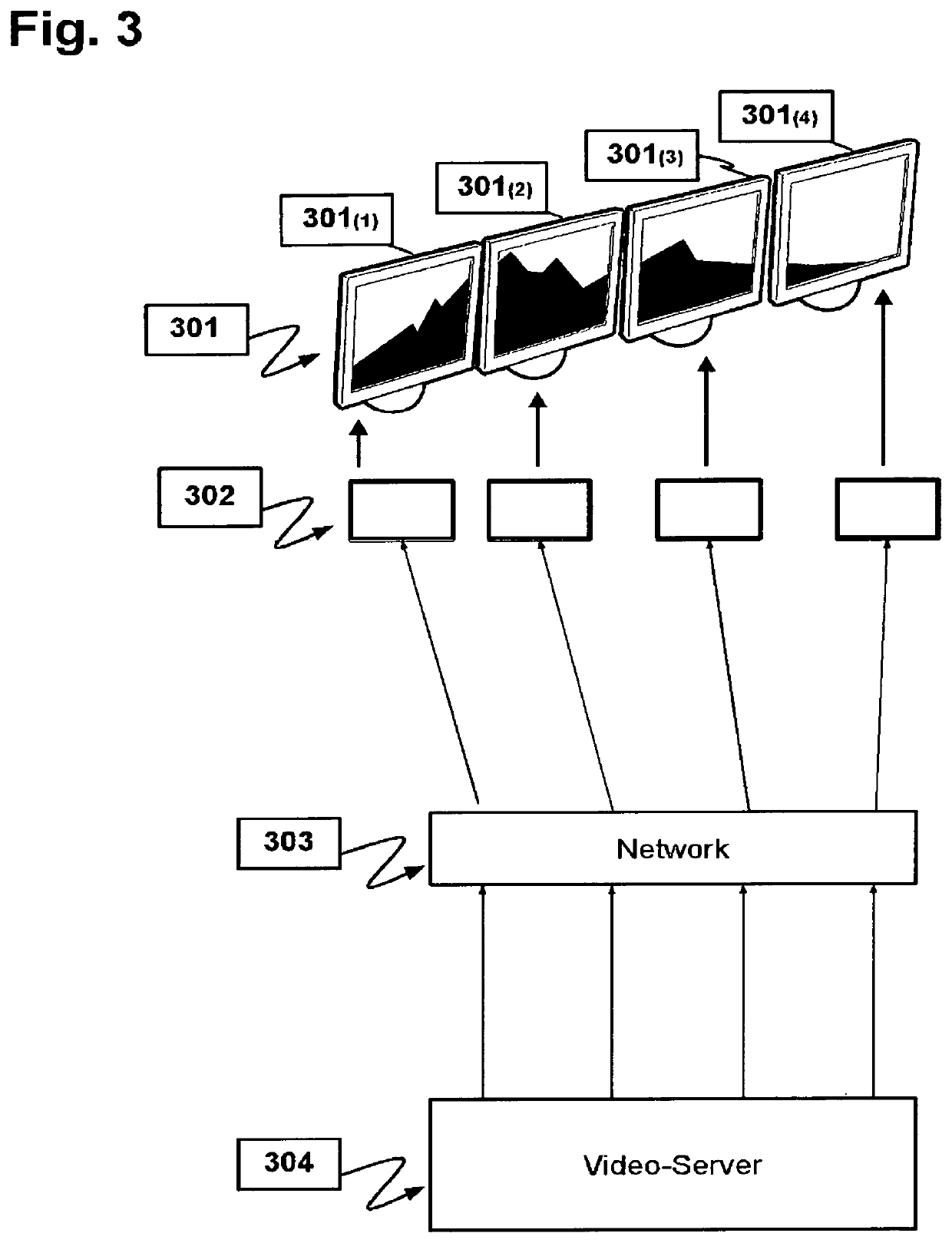
Whereas in the disclosed method, where a sequence of video frames is chopped into sub-image sequences and separately modified, encoded, and streamed, the total resolution is limited only by the capabilities of the much more powerful video-server.
Non-realtime video streaming is commonplace with internet services such as Netflix but these services tend to impose multi-second delays during transmission due to the nature of TCP / IP communications and the addition of buffering.
The first challenge in synchronization is to achieve sub-millisecond latency in the processing, chopping, and splitting of frames on the server.
The second challenge is achieving the right encoding parameters (compression, bitrate) that are compatible with multiple network display adapters.
The third challenge is ensuring that the streaming occurs in such a way that the network display adapters are able to play back the frames perfectly synchronized with optimized latency (to the devices and network conditions).
The mere inclusion of individual sub-image time stamps is insufficient to achieve this synchronization as additional latency has been incurred since the video was streamed by the server (including the sending, receiving, decoding, and output by the network display adapter), which must be taken into account.
However, depending on network quality and any variation between network display adapters and the image sizes of the relative portions, such playback is typically not perfectly synchronized.
However this last approach means the displays must be within a display-cable length of the video-server and the number of displays is limited by the capacity of the video-server to accommodate additional video cards.
Software clocks running on different computers typically don't run at the exact same speed hence time drift frequently occurs even with identical hardware over time and can even change with temperature changes or as CPU clock speed changes to adapt to local conditions (power demand, processor load, etc).

Method used


Image

  • System and method for synchronized streaming of a video-wall
  • System and method for synchronized streaming of a video-wall
  • System and method for synchronized streaming of a video-wall

Examples


Embodiment Construction

[0037]This networked video-wall invention efficiently splits the sequence of frames of a video source on-the-fly and distributes the resulting streams of compressed video sub-frames over the network to multiple listening display devices where the corresponding sub-frames of an original frame are all displayed in synchrony. The splitting is achieved by built-in algorithms that decode, parse, process, and re-encode each input frame into multiple sub-images for transmission and display. There is no theoretical limit on the size of the video-wall, and each display can be independently positioned and oriented (i.e. rotated) within the video-wall.

[0038]Because only the relevant portions of the image are being sent to each display, and each of the video streams are encoded for network transmission, the network bandwidth consumed can be minimized and the ultimate resolution of the video-wall is not constrained by network bandwidth or SOC resolution limitations.

[0039]The present disclosure d...


PUM


Abstract

A system is disclosed for processing and streaming real-time graphics by a video-server for synchronized output via secondary-network connected display adapters to multiple displays arranged as a video-wall. This system enables the video-server to leverage performance advantages afforded by advanced GPUs, combined with low-cost Smart displays or System-on-Chip devices to deliver advanced realtime video-wall capabilities over the network while offering flexibility in the selection of network display adapters and still achieving synchronized output of multiple sub-image streams to selected end-point displays. This has applications generally in the field of real-time multiple-display graphics distribution as well as specific applications in the field of network video-walls. A method and computer readable medium are also disclosed that operate in accordance with the system.

Description

CROSS-REFERENCE TO RELATED APPLICATION[0001]This application claims priority from the U.S. Provisional Patent Application No. 62 / 980,026 filed on Feb. 21, 2020, which is hereby incorporated by reference.FIELD OF INVENTION[0002]Large electronic displays may be formed from an array of digital displays referred to as a “video-wall”. For example video-wall might be comprised of a 3×3 array of nine displays, each simultaneously displaying a portion of a single image, thereby creating the appearance of a single large display. It is generally desirable both to have full flexibility in the arrangement of displays, and the ability to update the displays with realtime content streamed over the network to the display. The present invention relates generally to improving the setup and operation of network addressable video-wall displays.BACKGROUND OF THE INVENTION[0003]The present invention relates generally to improving the setup and operation of video-wall displays and particularly to network...

Claims


Application Information

Patent Timeline
Patent Type & Authority Applications(United States)
IPC IPC(8): G06F3/14H04L29/06H04N21/43
CPCG06F3/1446G06F3/1431H04N21/4307H04L69/28H04N21/242G09G2300/026G09G2356/00G09G2360/122G09G2370/042G06F3/1454G09G2370/022G09G2350/00G09G2320/0252G09G5/363G09G5/12
Inventor GRIFFIN, TIMOTHY
Owner USERFUL CORP
Why Eureka
Try Eureka