Data transmission apparatus and data transmission method

a data transmission apparatus and data transmission technology, applied in the direction of digital transmission, orthogonal multiplex, multiplex communication, etc., can solve the problems of difficult to maintain the orthogonality between codes, and impossible to maintain the orthogonality of codes

Inactive Publication Date: 2004-03-04
PANASONIC CORP
View PDF2 Cites 47 Cited by
  • Summary
  • Abstract
  • Description
  • Claims
  • Application Information

AI Technical Summary

Benefits of technology

0009] It is an object of the present invention to provide data transmission apparatus and data transmission method that can maintain orthogonality of codes even when spreading factors are different at the time of carrying out two-dimensional spreading of frequency axis direction and time axis direction, in addition, it is possible to optimize spreading factors of frequency axis direction and time axis direction of each code while maintaining orthogonality of codes.

Problems solved by technology

However, in the apparatus described above, when two-dimensional spreading is carried out in OFDM, although normal orthogonal code is used in executing spreading, there is a difficult problem to maintain the orthogonality between codes after performing multiplexing of signals of different spreading factors.
In other words, when two-dimensional spreading is carried out in OFDM, there is a difficult problem to maintain orthogonality between codes because there is a premise condition that both frequency axis direction and time axis direction are of similar spreading factor in the orthogonal signal after being multiplexed and subjected to a plurality of spreading even when a normal orthogonal code is used to carry out spreading under the condition that both / either of frequency axis direction and / or time axis direction of signals of different spreading factors are multiplexed.
In CDMA, because orthogonality of codes has large influence on the capacity, it is impossible to maintain the orthogonality of codes as the frequency axis direction and time-axis direction are not of the same spreading factor as described in the aforementioned apparatus even if orthogonality between codes is preserved when using different spreading factors among users.

Method used


Image

  • Data transmission apparatus and data transmission method
  • Data transmission apparatus and data transmission method
  • Data transmission apparatus and data transmission method

Examples


assignment example 2

[0038] First, assignment example 2 of different total spreading factors is the case of assigning two-dimensional spreading code in which spreading factors of frequency axis direction are similar and spreading factors of time axis direction are different. Here, 6 code patterns 1 to 6 shown in FIG. 6 are formed as a chip allocation diagram shown in FIG. 5 (4 chips in frequency axis, and 8 chips in time axis).

[0039] The code patterns 1 to 6 shown in FIG. 6(A) to FIG. 6(F) represent the case where spreading factors of frequency axis directions are common to all (SFf=4), and spreading factors of time axis directions are 2, 4, 8, 8, 4, and 2 (SFt=2, 4, 8, 8, 4, 2), respectively. Here, orthogonal codes A and B of 2 chips which are mutually orthogonal with a spreading code of twice of the spreading code corresponds to frequency axis direction are considered as basic codes similar to the case of assignment example 1. Two-dimensional spreading code corresponds to code pattern 1 is SFf=4, SFt=...

assignment example 3

[0042] First, assignment example 3 of different total spreading factors is the case of assigning two-dimensional spreading code in which the spreading factors of time axis direction are similar and spreading factors of frequency axis direction are different. Here, four code patterns 1 to 4 shown in FIG. 8 are formed as a chip allocation diagram shown in FIG. 7 (8 chips in frequency axis, and 4 chips in time axis).

[0043] The code patterns 1 to 4 shown in FIG. 8(A) to FIG. 8(D) represent the case where spreading factors of time axis directions are common to all (SFt=4), and spreading factors of frequency axis directions are 2, 4, 8, and 8 (SFt=2, 4, 8, 8), respectively. Here, orthogonal codes A and B of 2 chips which are mutually orthogonal with a spreading code of twice of the spreading code corresponds to frequency axis direction are considered as basic codes similar to the case of assignment example 1. Two-dimensional spreading code corresponds to code pattern 1 is SFf=2, SFt=4, an...

assignment example 4

[0046] Next, assignment example 4 of different total spreading factor is the case of assigning two-dimensional spreading code in which the spreading factors of frequency axis direction and spreading factors of time axis direction are different. Here, four code patterns 1 to 4 shown in FIG. 10 are formed as a chip allocation diagram shown in FIG. 9 (4 chips in frequency axis, and 8 chips in time axis).

[0047] The code patterns 1 to 4 shown in FIG. 10(A) to FIG. 10(D) represent the case where spreading factors of frequency axis directions are 2, 4, 2, and 4 (SFf=2, 4, 2, 4), and spreading factors of time axis directions are 2, 4, 8, and 8 (SFt=2, 4, 8, 8), respectively. Here, orthogonal codes A and B of 2 chips which are mutually orthogonal to spreading code of twice of spreading code corresponds to frequency axis direction are considered as basic codes similar to the case of assignment example 1. Two-dimensional spreading code corresponds to code pattern 1 is SFf=2, SFt=2, and total s...


PUM


Abstract

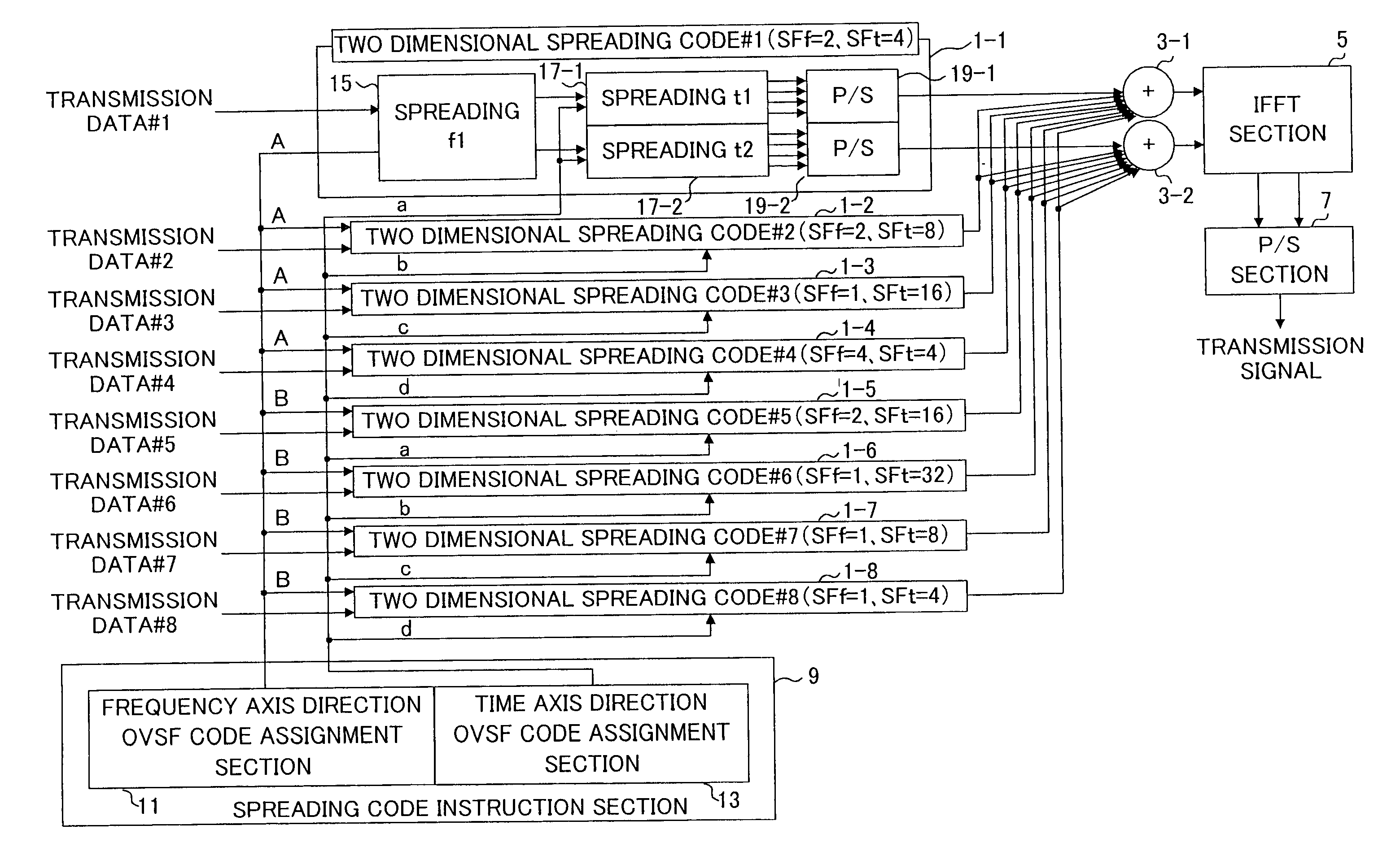
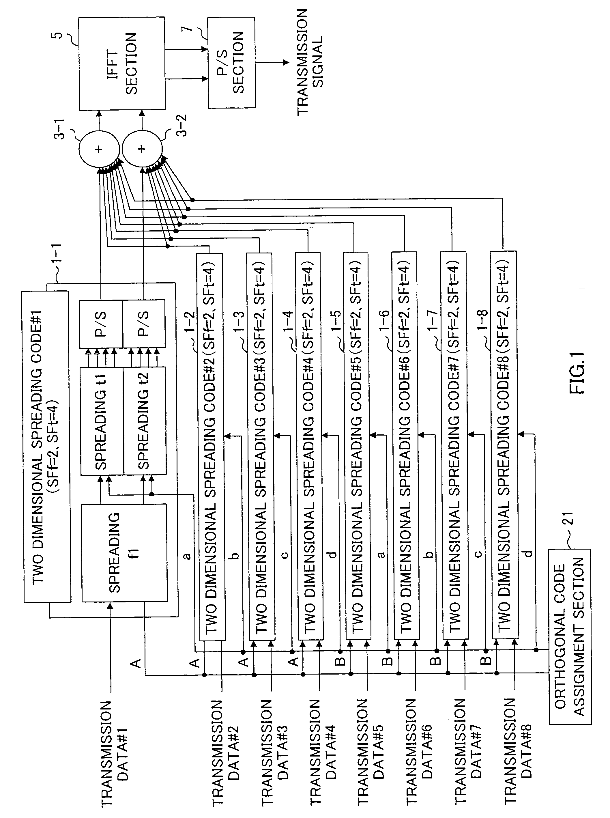
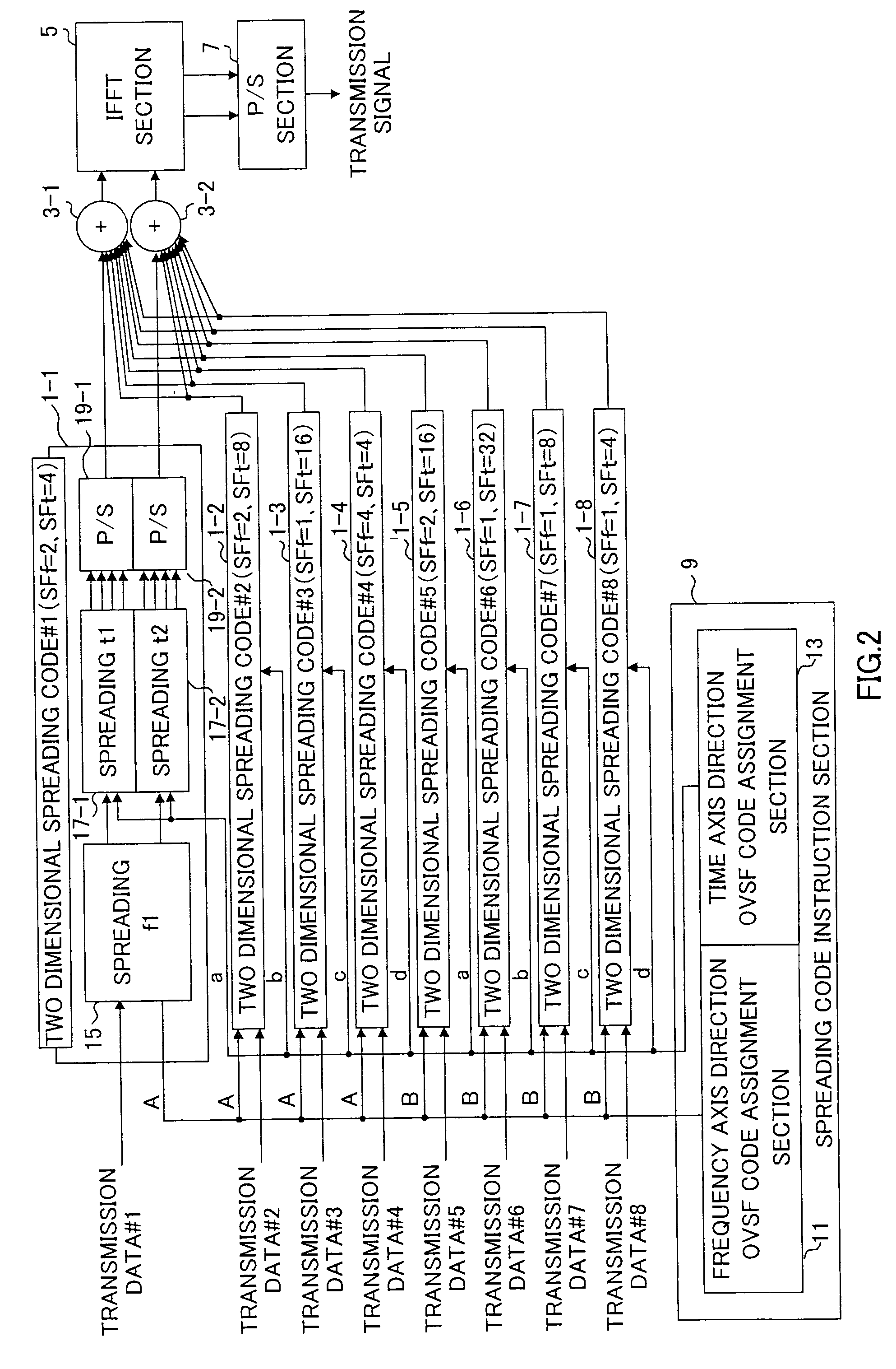
An orthogonal variable spreading factor (OVSF) of one dimension represented by coding tree is extended into two dimensions and applied simultaneously in both directions, frequency axis direction and time axis direction when carrying out spreading of two dimensions of frequency axis direction and time axis direction. For example, the transmission data is first spread by OVSF code of one dimension in the frequency axis direction (obtained from frequency axis direction OVSF code assignment section 11), and the result is spread by OVSF code of one dimension in time axis direction (obtained from time axis direction OVSF code assignment section 13, which is selected independent of frequency axis direction) in each of two-dimensional spreading sections 1-1 to 1-8.

Description

[0001] The present invention relates to data transmission apparatus and data transmission method.[0002] Recently, a technique / method for transmission a high-speed data of different types such as image, voice, etc. in fields such as mobile communication or digital broadcasting etc. is considered extensively. Thus, the OFDM (Orthogonal Frequency Division Multiplexing) method and CDMA (Code Division Multiple Access) method which are combined together to perform OFDM-CDMA method recently attracts attention in the mobile communication field because of strong reason in frequency selective fading. The OFDM method is one measuring technique of frequency selective fading, further, it is one kind of multicarrier modulation method to achieve mutual orthogonality between a plurality of subcarriers (carrier waves), and there is a high-order modulation method which has the most frequency utilization efficiency among multicarrier modulation methods. In addition, the CDMA method similarly is one me...

Claims


Application Information

Patent Timeline
Patent Type & Authority Applications(United States)
IPC IPC(8): H04B1/692H04J11/00H04J13/00H04J13/12H04J13/20H04L5/02
CPCH04J13/0044H04L5/026H04J13/12H04J13/102
Inventor UESUGI, MITSURUINOGAI, KAZUNORISUMASU, ATSUSHI
Owner PANASONIC CORP
Why Eureka
Try Eureka