
Generation of orthogonal codes

Inactive Publication Date: 2005-10-27
TELEFON AB LM ERICSSON (PUBL)
View PDF12 Cites 20 Cited by
  • Summary
  • Abstract
  • Description
  • Claims
  • Application Information

AI Technical Summary

Benefits of technology

[0024] Also, only simple logic operations are performed by the logic unit and the corresponding step, respectively, thereby eliminating the need for storing and complex processing means / steps and thus further reducing implementational complexity (no RAM / DSP / address bus necessary etc.). In addition, since neither a program needs to be executed in order to calculate the desired codeword nor any intermediate storage of the codeword is required, the overall delay caused by code generation is reduced to a significant extent so that a fast initialization as well as a quick restart of code generation becomes possible.
[0038] According to claim 11, each of the p code generators is provided with a dedicated counter. While increasing complexity when compared with the implementation according to claim 10, this allows for an asynchronous operation of the p code generators, where the first code bits of the codewords are not necessarily output at the same time.

Problems solved by technology

While having the benefit of being able to quickly restart code generation at any time in case of synchronization inconsistencies (by resetting the DSP and / or the RAM), this approach requires a high processing power (DSP), a high complexity in terms of the required hardware (DSP, RAM, a large width of the address buses to / from the RAM (depending on the maximum spreading factor to be supported and the width of each memory location]), and many DSP write cycles to initialise the RAM, i.e. to completely write the desired codeword into the RAM.

Method used


Image

  • Generation of orthogonal codes
  • Generation of orthogonal codes
  • Generation of orthogonal codes

Examples


first embodiment

[0067]FIG. 6 shows a block diagram of a code generator 60 according to a first embodiment of the invention. Herein, the code to be generated (also referred to as the desired codeword) is identified by the spreading factor (length) SF and the index k, as described above with respect to the prior art. It is assumed that SF is selectable from values in the range SFmin≦SF≦SFmax, wherein SFmin and SFmax denote a minimum and a maximum spreading factor, respectively.

[0068] Optionally, the code generator 60 is configurable so as to generate a particular type of orthogonal code selected from a set of types including, e.g., OVSF, Hadamard, and Walsh codes. In this case, the desired type of the orthogonal code is indicated by an additional input, the mode signal m, as indicated by the dashed arrow in FIG. 6. Otherwise, the code generator 60 is suitable f or generating a single type of orthogonal code only and thus does not require a mode input.

[0069] Based on the inputs SF, k, and optionally...

second / third embodiment

Second / Third Embodiment

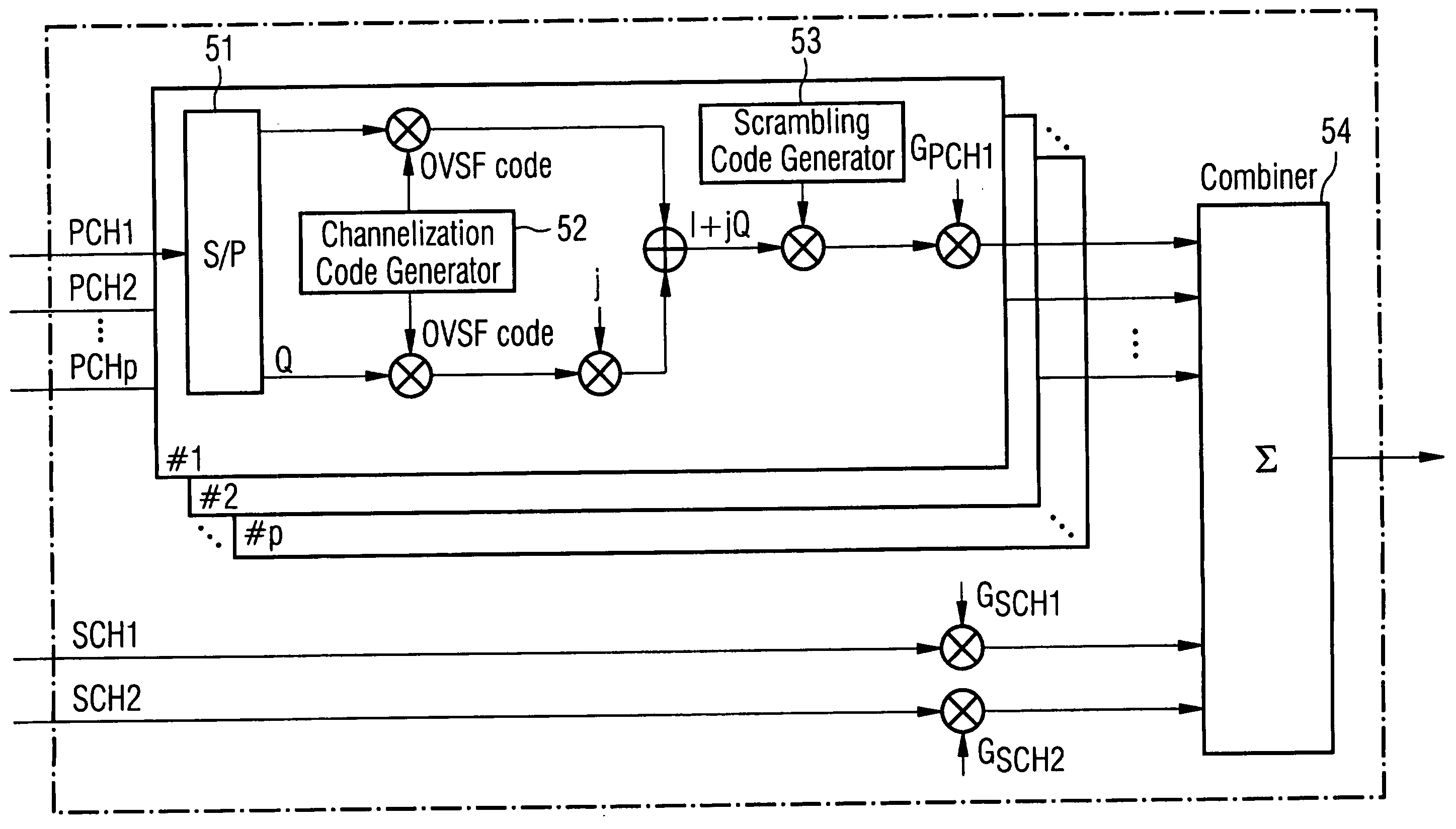
[0102]FIG. 9 shows a block diagram of a parallel code generator according to a second embodiment of the present invention. It is assumed that the parallel code generator 90 must be capable of generating, in the same period of time (i.e concurrently / simultaneously), a total of p>1 codewords. It should be noted that p may assume rather high values. For example, in different UMTS projects run by the applicant, p has a value of 1194 and 1636, respectively. Each codeword is identified by a spreading factor SFq, an index kq, and an optional mode signal mq indicating the desired type of code (OVSF / Hadamard / Walsh etc.). wherein q=1, 2, . . . , p. Let SFmax=2N denote the maximum spreading factor (maximum length) of all codes to be generated, i.e.

SFq≦SFmax for q=1, 2, . . . , p.

[0103] As can be seen from FIG. 9, a set of p code generators 90-1, 90-2, . . . , 90-p is provided, wherein each code generator includes an index conversion unit 91-q as well as a logic unit 92...


PUM


Abstract

A code generator and method for generating an orthogonal code for use in the baseband part of a transmitter or transceiver of a telecommunication system. An index conversion unit converts an index (k) into a modified index (j) associated with a corresponding code having a spreading factor greater than one and less than or equal to a maximum spreading factor. A logic unit performs logic operations on bits of the modified index (j) and a counter value (i) to generate a code bit of the orthogonal code. A number of parallel code generators may generate a number of orthogonal codes having respective spreading factors and indices.

Description

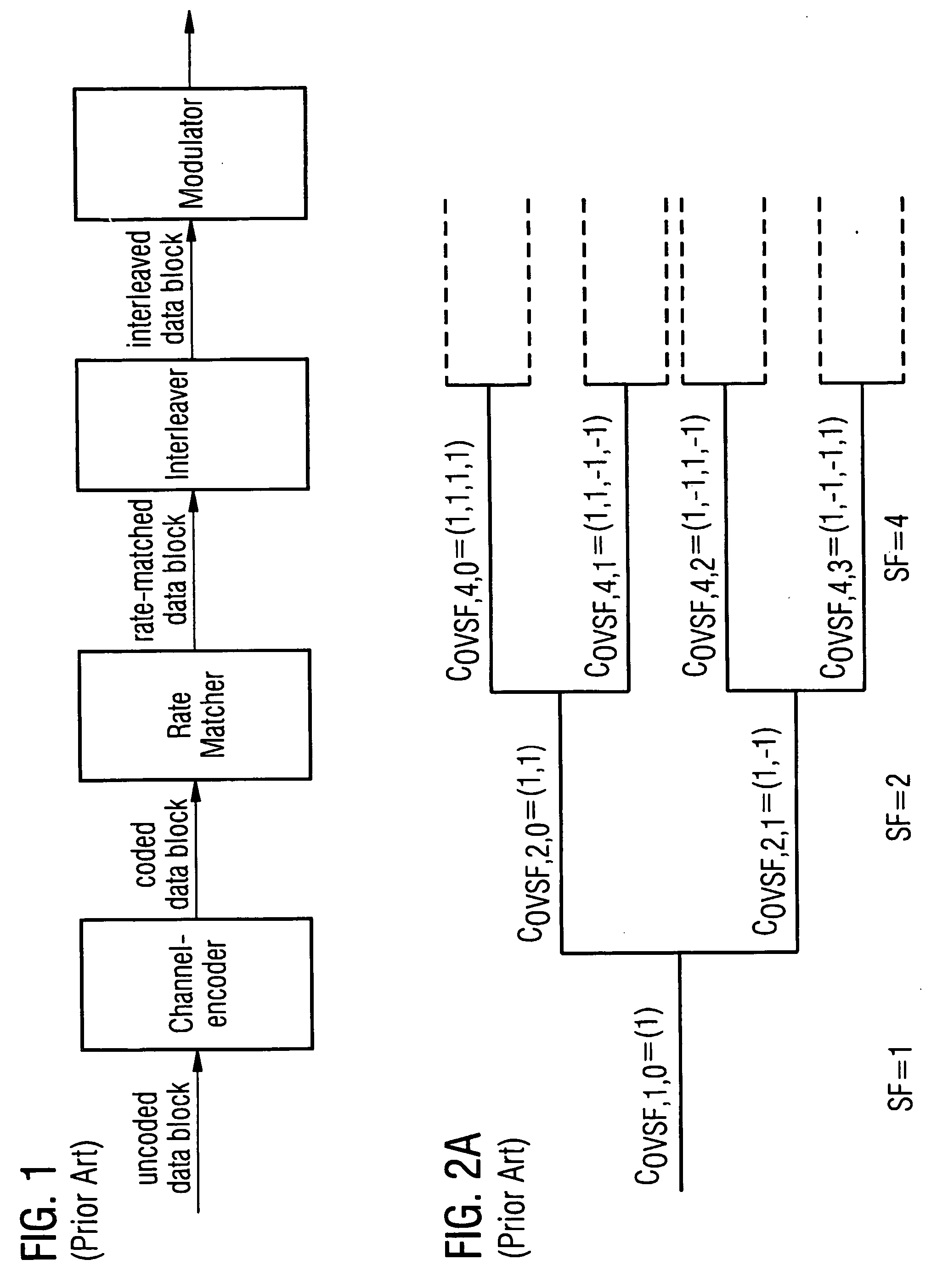
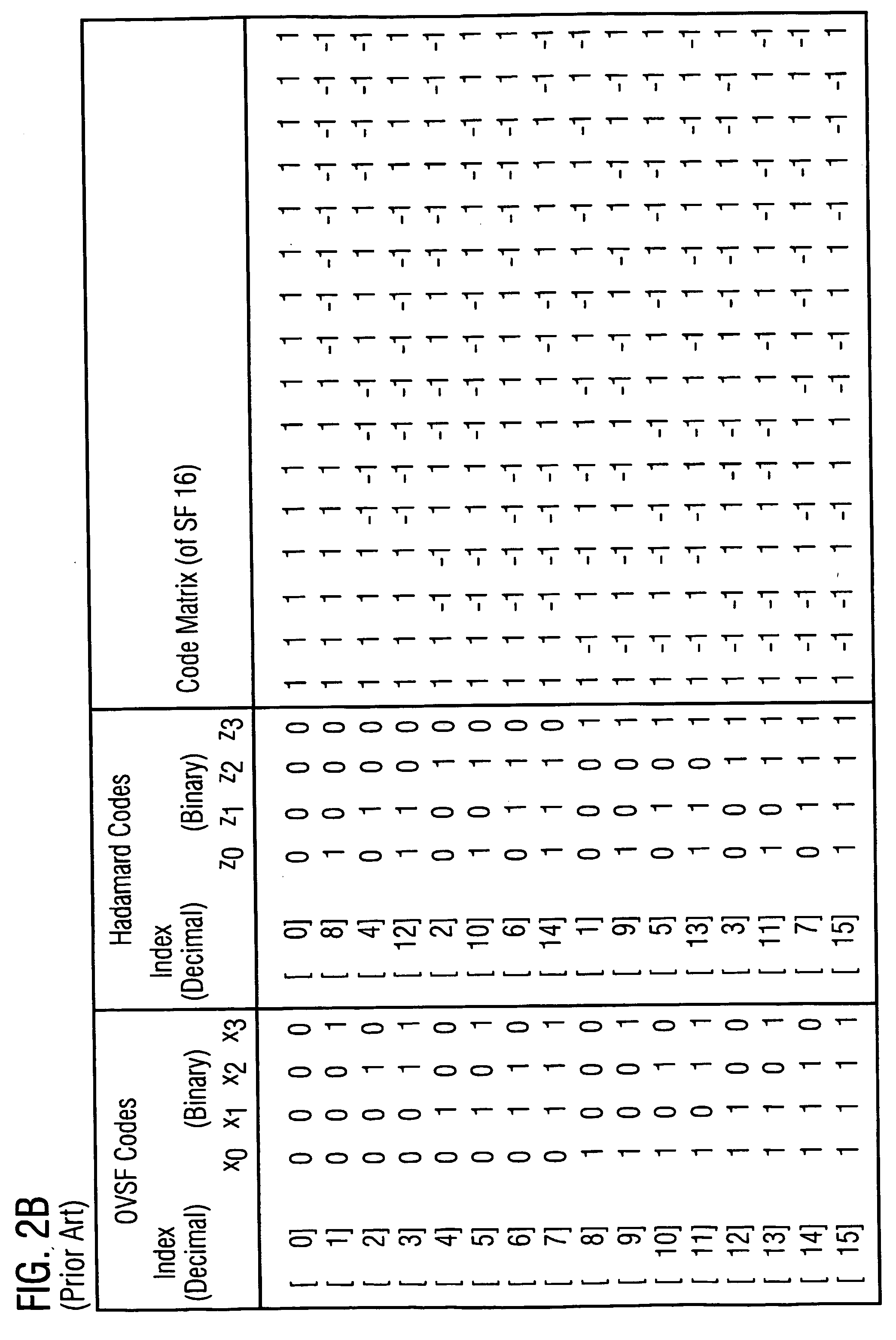
FIELD OF THE INVENTION [0001] The present invention relates to the generation of orthogonal codes such as “orthogonal variable spreading factor” (OVSF) codes, Hadamard-codes, Walsh codes etc. . . . More particularly, the present invention relates to improved code generation apparati and methods for application in, e.g., the baseband part of a transmitter or a transceiver of a telecommunication system. DESCRIPTION OF THE PRIOR ART [0002] A transmitter for use in a digital telecommunication system is known, for instance, from 3GPP TS 25.212 V3.4.0 (September 2000) “3rd Generation Partnership Project; Technical Specification Group Radio Access Network; Multiplexing and channel coding (FDD) (Release 1999)”, section 4.2. In FIG. 1 of the present application, a block diagram of parts of such a transmitter is given. As shown, the transmitter includes a channel encoder, a rate matcher, an interleaver, and a (baseband) modulator, wherein the latter converts the interleaved data bits into sym...

Claims


Application Information

Patent Timeline
IPC IPC(8): H04J11/00
CPCH04J13/12H04J13/0044
Inventor PETTENDORF, HARTMUTFAULHABER, PAUL
Owner TELEFON AB LM ERICSSON (PUBL)
Learn More