
Heterogeneous gaseous chemical reactor catalyst

Inactive Publication Date: 2004-03-04
COMBS GLENN A
View PDF16 Cites 34 Cited by
  • Summary
  • Abstract
  • Description
  • Claims
  • Application Information

AI Technical Summary

Benefits of technology

[0032] It is an object of the invention to provide improved elements and arrangements thereof for the purposes described which is inexpensive, dependable and fully effective in accomplishing its intended purposes.

Problems solved by technology

Inefficient fluid flow can result in undesirable fluid friction losses.
However, increasing the GSA can lead to a pressure drop penalty that deleteriously affects the synthesis of hydrogen (and carbon monoxide).
Catalyst size and shape also impact on reformer gas pressure losses and catalyst strength, which likewise influences practical useful catalyst life.
One difficulty with this catalyst shape is that it cannot be produced in small diameters as rings where the diameter to height ratio is substantially less than 1.5:1 to achieve higher geometric surface area or to lower pressure drop because the hole sizes become too small, rendering the catalyst difficult to manufacture.
The '990 catalyst particles comprise of shapes with smaller geometric surface area than multi-holed axial cylindrical ring catalyst shapes of comparable catalyst size with a concomitant deleterious impact on catalyst activity.
Such a non-rigid, porous, fibrous catalyst would be difficult to produce in commercial quantities because of the small size and characteristic shape of the interior discrete flow channels.
Increasing the overall external catalyst particle dimensions (diameter, height or both) results in a greater loaded catalyst void fraction resulting in lower gas pressure drop.
Increasing the loaded catalyst void fraction is not necessarily desirable because it can lead to turbulence problems affecting reactants heat transfer, mixing and residence time in the catalyst.

Method used


Image

  • Heterogeneous gaseous chemical reactor catalyst
  • Heterogeneous gaseous chemical reactor catalyst
  • Heterogeneous gaseous chemical reactor catalyst

Examples


example 2

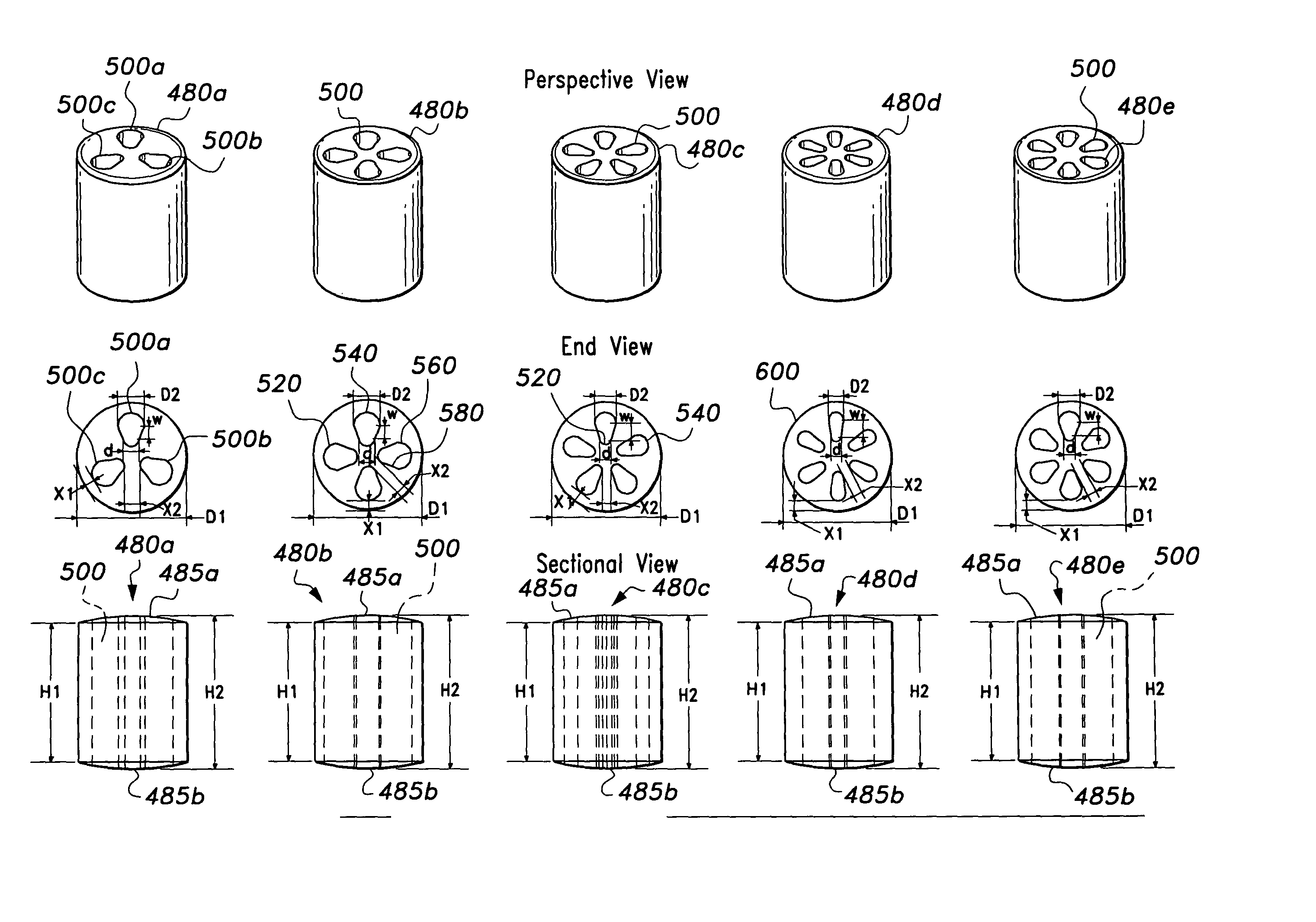
[0101] FIG. 9 shows separate perspective, top and bottom, and elevation views of cylindrical catalyst rings 680, and more specifically cylindrical catalyst rings 680a, 680b, 680c, and 680d according to the invention. The cylindrical catalyst ring 680 may optionally defined curved or domed opposite ends 685a and 685b. The ends 685a and 685b may be spherical, ellipsoidal or another curved shape, or may be flat and circular. The cylindrical catalyst rings 680a, 680b, 680c, and 680d define at least one internal generally elliptical shaped hole 700 that runs right through the cylindrical ring 680 to emerge at both ends of the ring 680. For example, the cylindrical ring 680a defines four internal elliptical shaped holes 700a, 700b, 700c and 700d. It is preferred that the cylindrical ring 680 defines at least three internal elliptical shaped holes 700. Each at least one internal elliptical shaped hole 700 has a length 705 and a width 707. The dimensions 705 and 707 may be increased or decr...

example 3

[0103] FIG. 11A shows separate perspective, top and bottom, and elevation views of cylindrical catalyst rings 780, and more specifically cylindrical catalyst rings 780a, 780b, and 780c according to the present invention. The rings 780a, 780b, and 780c define at least one generally L-shaped hole 800. For example, the axial L-holed cylindrical ring 780c defines four L-shaped holes 800a, 800b, 800c and 800d. It is preferred that the axial L-hole cylindrical ring 780 defines at least two L-shaped holes 800. Each at least one L-shaped hole 800 has a length 705 and a width 707. The catalyst 780 may optionally defined curved or domed opposite ends 785a and 785b. The ends 785a and 785b may be spherical, ellipsoidal or another curved shape, or may be flat and circular.

[0104] With respect to FIG. 11B the L-shaped holes are formed of circular or other curve shape hole ends 51' and 52', having widths 43' and 46'. Widths 43' and 46' are generally, but not necessarily of equal length. FIG. 11B sh...

example 4

[0107] FIG. 13A shows separate perspective, top and bottom, and elevation views of cylindrical catalyst rings 880, and more particularly cylindrical catalyst rings 880a, 880b, and 880c according to the present invention. The catalyst 880 may optionally defined curved or domed opposite ends 885a and 885b. The ends 885a and 885b may be spherical, ellipsoidal or another curved shape, or may be flat and circular.

[0108] Still referring to FIG. 13A, the rings 880a, 880b, and 880c define at least one internal generally rounded-diamond-shaped hole 900. For example, the axial rounded-diamond-holed cylindrical ring 880b defines five generally rounded-diamond-shaped holes 900a, 900b, 900c, 900d and 900e. It is preferred that the axial rounded-diamond-holed cylindrical ring 880 defines at least three rounded-diamond-shaped holes 900.

[0109] FIG. 13B shows a top view of an axial rounded-diamond-hole 900. The axial rounded-diamond-hole 900 defines end curves 64' and 64A', having widths 65' and 66'...


PUM

PropertyMeasurementUnit
Circumferenceaaaaaaaaaa

Abstract

An improved heterogeneous catalyst for catalyzing the reaction of gaseous reactants, comprising a high performance catalyst particle with a diameter to height ratio in the range between about 0.5:1 to 1.0:1.0, the high performance catalyst particle has a Relative Particle Size Parameter (RPSP) and a Geometric Surface Area (GSA), wherein the high performance catalyst particle has a higher GSA for a particular RPSP than a prior art catalyst particle. In another embodiment the improved heterogeneous catalyst with a diameter to height ratio in the range between about 0.5:1 to 1.0:1.0 has a Relative Particle Size Parameter (RPSP), a Geometric Surface Area (GSA), and an associated Relative Pressure Drop (RPD), wherein the high performance catalyst particle has a higher GSA for a particular RPSP or alternately a lower RPD for a particular GSA than a prior art catalyst particle.

Description

[0001] This application claims the benefit of U.S. Provisional Patent Application Serial No. 60 / 402,580, filed Aug. 12, 2002.1. FIELD OF THE INVENTION[0002] The present invention is directed to advanced catalyst shapes that increase catalyst performance while reducing gas pressure drop.2. BACKGROUND OF THE INVENTION[0003] Catalysts are employed in chemical reactors to promote the conversion of reactants to desired products. Good catalysts induce rapid transformation of chemical molecules to combine into different molecules while the catalyst itself is not expended or altered.[0004] A catalyst that exists in a different phase as the chemical reactants is called a heterogeneous catalyst such as a solid catalyst used to transform gaseous reactant molecules to a useful gaseous product such as hydrogen. A heterogeneous catalyst system comprises a plurality of heterogeneous catalyst particles. Each heterogeneous catalyst particle typically comprises internal voids such as holes that trave...

Claims


Application Information

Patent Timeline
IPC IPC(8): B01J23/755B01J23/78B01J23/83B01J35/00B01J35/02C01B3/40
CPCB01J23/755B01J2219/32279B01J23/83B01J35/002B01J35/026C01B3/40C01B2203/0233C01B2203/0244C01B2203/0844C01B2203/1005C01B2203/1011C01B2203/1047C01B2203/1052C01B2203/1247C01B2203/142C01B2203/82B01J23/78Y02P20/52B01J35/50
Inventor COMBS, GLENN A.
Owner COMBS GLENN A
Learn More